
Android talks to Arduino board
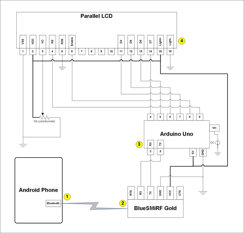
This project integrates an Arduino Uno with an LCD display and an Android device for Bluetooth communication. The main components involved include the Arduino Uno microcontroller, a Bluetooth module (typically an HC-05 or HC-06), and a compatible LCD display (such as a 16x2 character LCD).
To begin, the Arduino Uno is programmed to establish a Bluetooth connection using the Bluetooth module. The Arduino sketch should be set up to initialize the serial communication with the Bluetooth module, typically using the SoftwareSerial library to allow communication on different pins. The Bluetooth module will receive data from the Android app and send it to the Arduino.
The LCD is connected to the Arduino using the appropriate pins, usually employing the LiquidCrystal library for control. The LCD will be configured to display the received messages. When a message is sent from the Android app, it is transmitted via Bluetooth to the Arduino. The Arduino reads the incoming data and displays it on the LCD screen.
The Android app must be modified to allow for the sending of messages through the Bluetooth connection. This involves adjusting the app's code to establish a Bluetooth connection with the HC-05/HC-06 module and implementing functionality to send the text input from the user to the Arduino. Once the message is sent and acknowledged by the Arduino, it can be displayed on the LCD, completing the communication loop.
This project serves as a practical demonstration of wireless communication between an Android device and an Arduino, showcasing the ability to transmit data in real-time and providing a foundation for further enhancements and applications, such as remote monitoring or control systems. The example sketch provided can be modified to incorporate additional features, such as multiple message types, user interfaces, or even integration with other sensors and devices.This project slightly modifies the Google Android sample app called Bluetooth Chat so you can type a message in the Android app and that same message will appear on an LCD attached to an Arduino Uno. 1. Run the Android Bluetooth Chat sample app (after we modify the app in this instructable). Type a message in the app`s text box and press the send button. The message you typed echoesonthe app display. Why Just an easy way to test the Arduino`s ability to not only receive messages from, but send messages to the Android phone. You can take the example sketch and change it however you want. 🔗 External reference
Related Circuits

Agy utilized the Lilypad Arduino and LEDs for the first time in a textile project called Blinky Bike Bag, merging her skills in fabric manipulation with electronics. The bike bag is constructed from umbrella material to ensure waterproofing and...
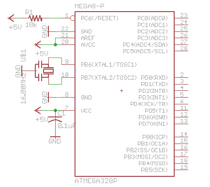
There are many bare-bones Arduinos available on the internet. Most of them are assembled on a solderless breadboard and utilize an ATmega168 (or ATmega328) microcontroller with an Arduino bootloader, a resonator (which may have built-in capacitors or require two...
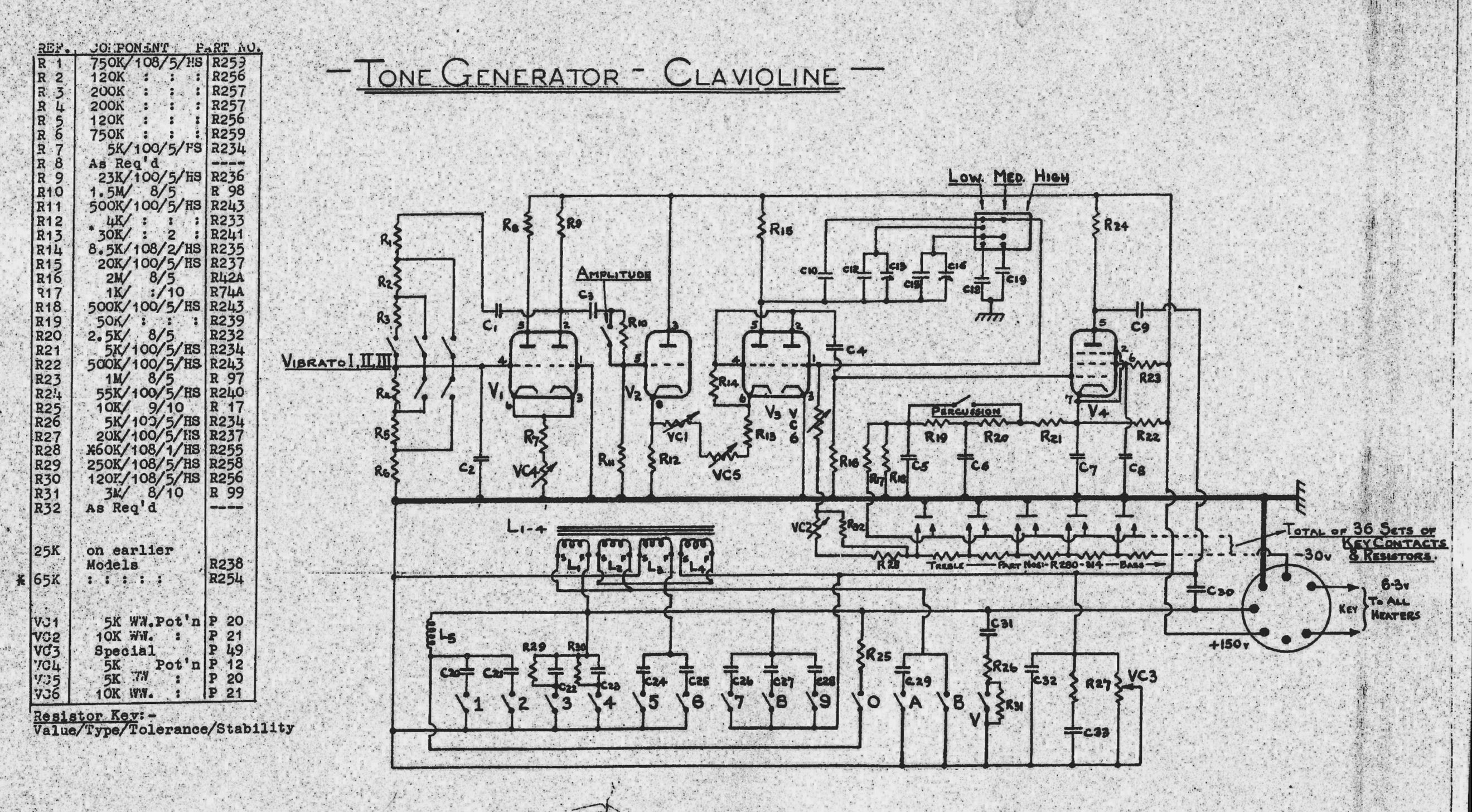
The Clavioline is an early electronic keyboard instrument, similar to the Hammond Solovox. Both instruments are monophonic (single-voiced) and tube-powered, consisting of a keyboard and an amplifier. The first image depicts a restored Clavioline, while the second shows a...
The MAX232 integrated circuit (IC4) is utilized for connecting to a PC via a serial port. This connection facilitates debugging and controlling the robot by allowing commands to be issued through the PC keyboard. However, during the robot's actual...
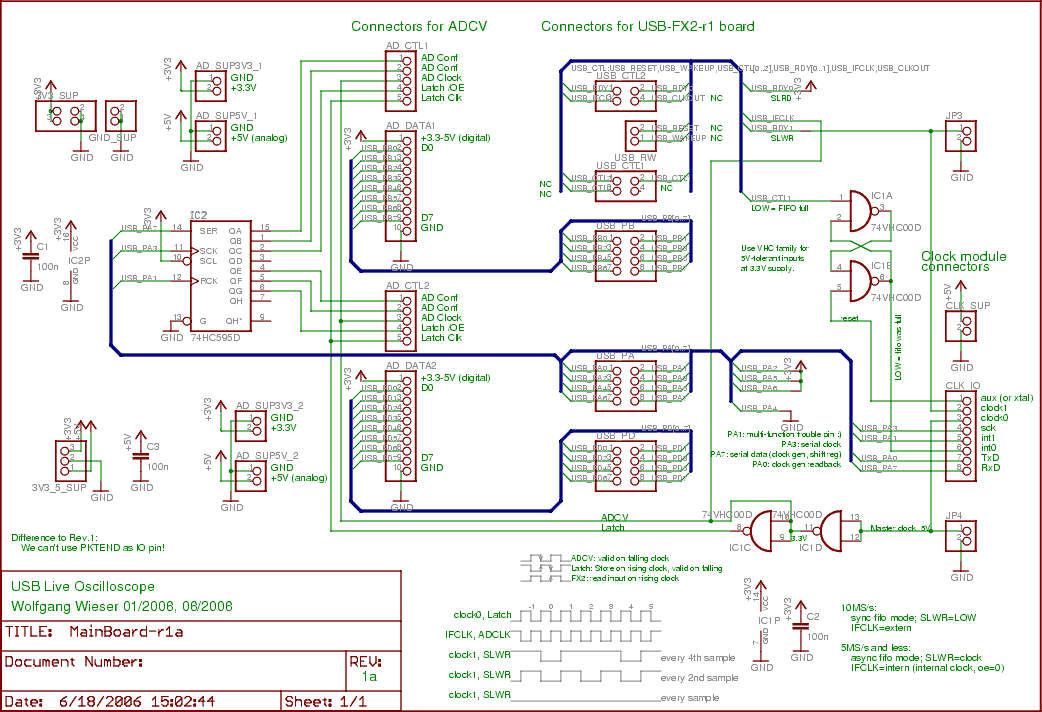
The two input boards (ADCV or digital) are connected to AD_CTL1, AD_DATA1, AD_SUP5V_1, and AD_SUP3V3_1 for the first board, with the second board using the same connections but with a suffix of 2. To transfer sampling data, the 16...
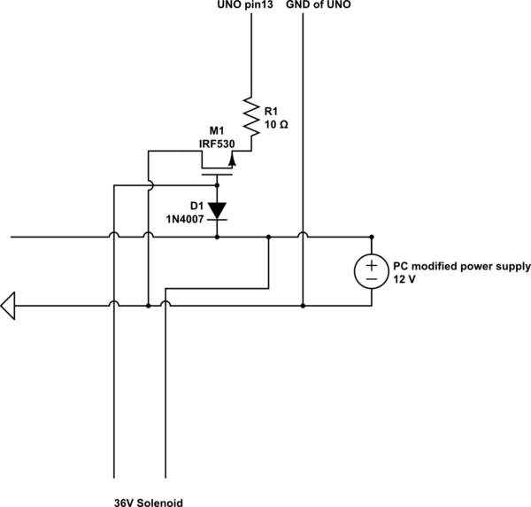
A 9 V DC battery initially powered the solenoid valve effectively. However, the solenoid did not generate sufficient force due to inadequate DC power. A modification was made to use a computer power supply as the power source. Providing...