
Angle of rotation detector
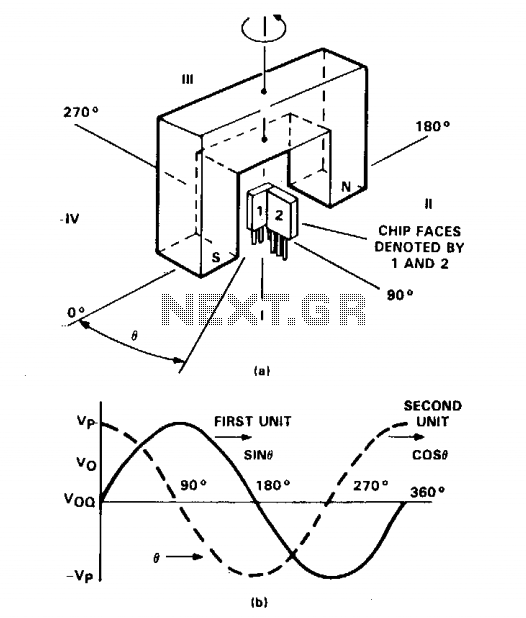
Additionally, sensor unit #2 decreases from its maximum output of +Vp at 0° to a minimum value of Vqq at 90°. Therefore, the output of sensor unit #1 represents a sine function of angle 0, while the output of unit #2 corresponds to a cosine function of angle 0, as depicted. Consequently, the first sensor provides the angle of rotation, while the second sensor indicates the quadrant location.
The circuit employs two TL3103 linear Hall-effect sensors, which are sensitive to the magnetic field generated by the U-shaped permanent magnet. The configuration of the sensors allows for precise angular measurement. The output from unit #1, which follows a sine function, effectively translates the rotation angle into a voltage signal that varies sinusoidally as the angle changes. This characteristic is particularly useful for applications requiring accurate angle detection.
Conversely, sensor unit #2, exhibiting a cosine function output, serves to determine the quadrant in which the rotational movement occurs. The maximum output of unit #2 at 0° signifies that the sensor is aligned with the magnetic south pole, while the gradual decrease to Vqq at 90° indicates a transition through the quadrants.
This dual-sensor arrangement is advantageous for applications such as robotics, automotive steering systems, and other precision control systems where both the angle of rotation and quadrant positioning are critical for functionality. The integration of these sensors into a control system can enhance the accuracy and responsiveness of the overall system, facilitating improved performance in real-time applications.The figure shows two TL3103 linear Hall-effect devices used for detecting the angle of rotation. The TL3103s are centered in the gap of a U-shaped permanent magnet. The angle that the south pole makes with the chip face of unit #1 is defined as angle 0. Angle 0 is set to 0° when the chip face of unit #1 is perpendicular to the south pole of the magnet. As the south pole of the magnet sweeps through a 0° to 90° angle, the output of the sensor increases from 0°.
Sensor unit #2 decreases from its peak value of + Vp at 0° to a value Vqq at 90°. So, the output of sensor unit #1 is a sine function of 0 and the output of unit #2 is a cosine function of 0 as shown. Thus, the first sensor yields the angle of rotation and the second sensor indicates the quadrant location.
🔗 External reference
Related Circuits
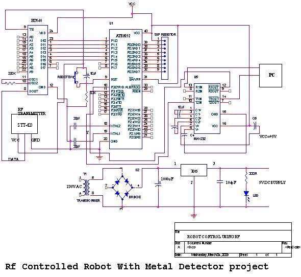
An embedded C-based RF-controlled robot equipped with a metal detector, along with wireless image and voice transmission capabilities. This project report is intended for electronics and communication engineering students. The project involves the design and implementation of an RF-controlled robot...
The circuit was constructed using a few components powered by a 9 V battery for sensing the presence of bugs transmitting within the frequency modulation range. Frequency Modulation (FM) transmits its signal or information over a carrier wave by...
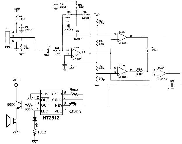
The presented schematic illustrates the construction of a simple PIR motion detector sensor. PIR sensors are capable of detecting motion and are primarily utilized to determine if a person has entered or exited the sensor's range. These sensors are...
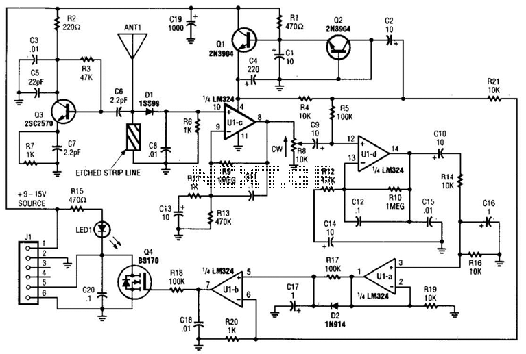
Operating at approximately 1.1 GHz, the detector senses disturbances in the electromagnetic field surrounding the antenna. The Doppler signal generated by detector D1 is amplified and used to control a power MOSFET switch. The antenna consists of a short...
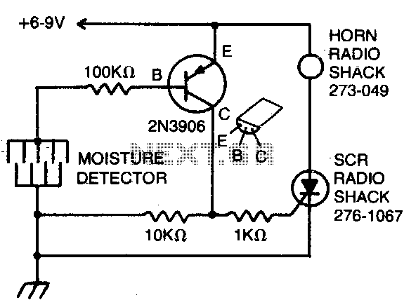
The detector consists of fine wires spaced approximately one to two inches apart. When the area between a pair of wires becomes moist, an alarm will sound. To deactivate the alarm, the DC power must be disconnected. The described moisture...

This circuit diagram represents a low-cost metal detector utilizing a single transistor circuit in conjunction with an old pocket radio. It operates as a Colpitts oscillator functioning within the medium band frequency range, with the radio tuned to the...
Warning: include(partials/cookie-banner.php): Failed to open stream: Permission denied in /var/www/html/nextgr/view-circuit.php on line 713
Warning: include(): Failed opening 'partials/cookie-banner.php' for inclusion (include_path='.:/usr/share/php') in /var/www/html/nextgr/view-circuit.php on line 713