
Animatronic Robot Head

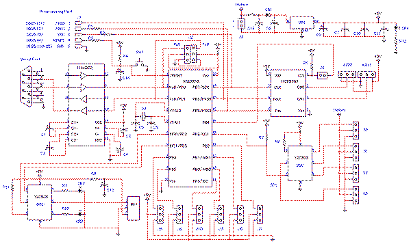
The schematic for the head mechanism incorporates various components essential for controlling the servos and ensuring synchronized movements. The servomotors are connected to a microcontroller, such as a PIC, which manages the input from the user or PC commands. Each servo is connected to a designated output pin on the microcontroller, allowing for precise control over their movements.
The power supply circuit should be designed to provide adequate voltage and current to the servos, typically 5-6V, depending on the specifications of the servos used. A voltage regulator may be included to ensure stable power delivery, especially if the servos draw significant current during operation.
The oz-ser chip, utilized for programming the servos, connects to the microcontroller via a serial interface. The MAX232 chip is used to convert the microcontroller's TTL signals to RS-232 levels, enabling communication with the PC. The push-buttons connected to the oz-ser chip allow for easy programming of movement sequences, with debouncing circuits potentially included to ensure reliable input.
The schematic should also include safety features, such as fuses or current limiting resistors, to protect the servos and control circuitry from overcurrent conditions. Additionally, proper grounding and decoupling capacitors should be implemented to minimize noise and ensure stable operation of the control signals.
In summary, the electronic schematic for the head mechanism integrates servos, a microcontroller, communication interfaces, and power management components to create a versatile and programmable robotic head capable of complex movements and animations.The head will be powered by servomotors and will be built from sheet plastic, metal or plywood. The template which can be used for cutting sheet material can be found at the end of this article. Download the template, compare the size of the printed servomotor with your servomotors at hand. Do the necessary resizing operations by photocopying the print, or you may directly print at the desired dimension. Copy the print onto the sheet material, you may use a simple carbon paper and do the copying by redrawing the lines by hand. The hand will apply some pressure on to the carbon paper and enable it to leave marks on the sheet material.
The marks will be the outlines of the template. Cut the marks with a thin plywood saw untill you complete all parts of the head. Sand them a bit to have nicer looking and well fitting parts. After cutting, assemble all pieces according to the renderings in this article. The head at this article is designed to be powered by 7 servos. So the eyes move independently looking to sides, up and down. The head can turn (look) right-left, up and down. The jaw can also move to do movements like speaking or laughing. The article continues with renderings, parts cutting template, various example circuits and microcontroller source codes. Read on, and don`t forget to add your comments ;) The opposite is of course possible. The number of servos can be reduced. to fore example 4 servos. With less servos, the cost of the head will be much lover though the most expensive parts are the servos.
The moving parts can be selected as you wish; either the head itself, eyes, or the jaw can move. The independent moving eyes can be connected to the same servo so turn to the same side. With oz ser 1 chip, you can use 6 onboard push-buttons to program 4 servos independently up to 32 steps of movement. The chip will drive the servos when the power is on and do a continuously repeat the given program. The program needn`t be 32 steps long. it can be less if desired. The program`s end can be changed via the onboard push buttons by the user. All the steps of the program can be altered whenever needed as well. If you want to build a PC controlled head, you can use a pic micro, connect it to a max232 type of chip.
Then write a code to the chip that will enable it to receive commands from the pc via its serial port and do the necessary operations on the servos. That is what our ozz ser RS4 and RS8 chips do. Oz-ser-rs8 chip receives coordinates for each servo. And position them one by one. It doesn`t save the positions and dependent on the pc. So that the chip can control up to 8 servos within programs sent by the pc. That means you can realise virtually (the pc hard disk is the limit) endless animations. oz-ser-rs8 Circuit schematic. 🔗 External reference
Related Circuits
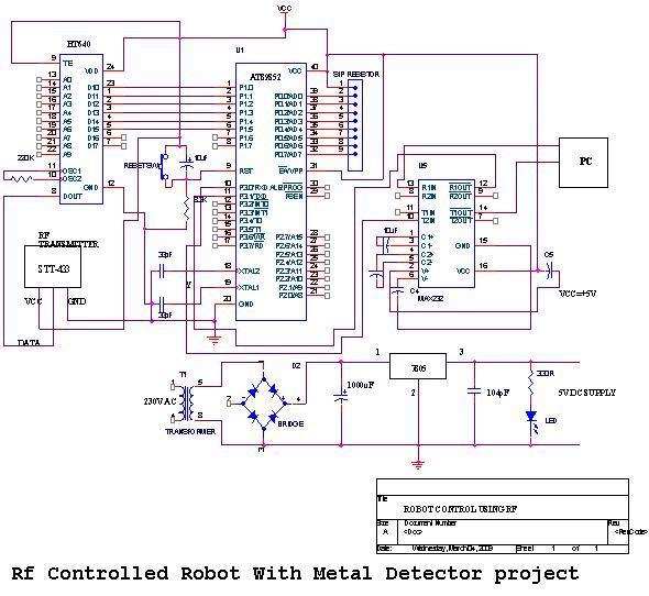
An embedded C-based RF-controlled robot equipped with a metal detector, along with wireless image and voice transmission capabilities. This project report is intended for electronics and communication engineering students. The project involves the design and implementation of an RF-controlled robot...
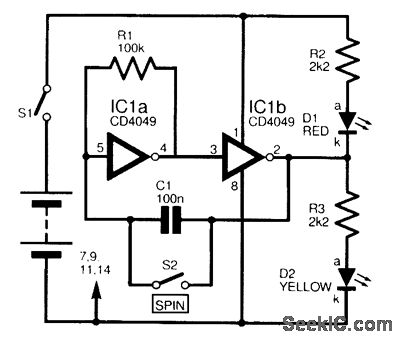
This circuit is designed to electronically simulate the tossing of a coin using a 4049 hex inverter integrated circuit (IC). It employs two of these ICs, specifically IC1a and IC1b, which are configured as an astable oscillator. This configuration...
The MiniBoard, a Motorola 68HC11 Robot Controller board designed by Fred G. Martin, also uses this driver. The day after, I then decided to prepare the page describing how to use C-52 EVB as a robot controller board. I...
Good preparation. There is one suggestion to use RFM70 or RFM22 for RF communication. The RFM70 and RFM22 are low-power, high-performance RF transceiver modules designed for wireless communication applications. Both modules operate in the 2.4 GHz ISM band, making them...
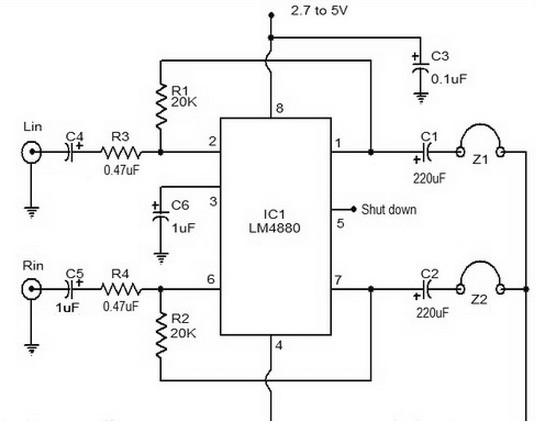
The LM4880 is a dual audio HiFi amplifier integrated circuit from National Semiconductor. This headphone amplifier circuit is specifically designed to produce high-quality audio output with a minimal number of components. The LM4880 integrated circuit is capable of delivering...
The Atmel AVR series consists of high-quality microcontrollers featuring a comprehensive instruction set, which has led to the development of numerous effective compilers, eliminating the need to learn assembly language. One notable compiler is the BASCOM/AVR from MCS Electronics,...