
AP500 and its application circuit ab
The AP500 dual-channel FET DC amplifier driver module is engineered for applications requiring high fidelity and robust power output. Its design incorporates advanced features that ensure reliability and performance in demanding audio environments. The low distortion and wide frequency response are critical for maintaining audio integrity, especially in high-power applications where signal fidelity is paramount.
The internal protection circuitry is a significant advantage, safeguarding the module during unexpected short circuits, thus enhancing the durability of the overall system. The ability to manage low frequencies effectively, combined with a gain of 27dB, positions the AP500 as a versatile component in various amplifier configurations.
The pin configuration is thoughtfully designed to facilitate easy integration into existing systems, with clear designations for power supply, signal input/output, and bias adjustments, allowing for straightforward implementation and customization. The module's low power consumption further simplifies design considerations, negating the necessity for additional heat management solutions.
Overall, the AP500 is a sophisticated solution for audio amplification needs, providing a reliable and high-performance option for engineers and designers working on high-power audio amplifier projects. Its capabilities in terms of output power, frequency response, and distortion control make it an ideal choice for both professional and consumer audio applications.AP500 is a high-performance dual-channel FET DC amplifier driver module. It uses a high operating voltage. Push power, low distortion, wide frequency response, simple external circuit, using the superior has unparalleled in the audio circuit resistance. AP500 can promote a greater power output, and the performance is very good, the circuit can easily use the system to make high-power amplifier circuit. AP500 internal structure of the pure DC output zero potential fairly stable, the operating voltage of 14 ~ 60V range, output zero drift is less than 90mV.
Its output has the protection circuit, even if it SPIDERS tube amplifier module will not be damaged when short circuit. AP500 has an excellent low frequency performance, the DC amplifier gain is still up to 27dB, so excellent low-frequency characteristics of the amplifier circuit to improve the transient index, lower distortion has great significance.
The electrical path limit operating voltage of 75V, not only provide a large output signal voltage, but also improve the dynamic characteristics of the circuit resistance. Since in-circuit DC structure, its input and output can be in the form of direct coupling. Application of the amplifier circuit in, AP500 can create OTLOCL, two, BTL, class AB, super CPI, CPI and other characteristics of the power amplifying circuit.
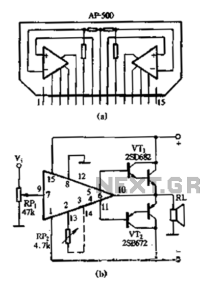
Due to the low power consumption of the module, use the heat sink is not required. Internal module also has an automatic zero word and distortion correction circuit distortion 0. 02%, conversion rates up to 70V/r./S, the closed-loop frequency response of 0 ~ work 500kHzo AP 500 module uses the single-line l 5 feet packaging, shape and pin arrangement shown in Figure 2-128 (a) the pin functions shown o be able to: 1 foot to the negative power supply; 23 feet for the static bias adjustment ends L channel; 4,5 L-sound Road discretionary signal output terminal; 6 feet for the negative feedback terminal L channel; 7 feet for the L-channel signal input; 8 feet for the ground; 9 feet for the letter R channel input terminal; 10 feet for the R sound was negative feedback terminal; 1 1,12 feet for R channel signal output terminal; 13,1 R 4 feet for sound channel static bias adjustment ends; 15 pin connected to the positive supply. Figure 2-12,8 (b) is its application circuit. This circuit uses a direct drive AP500 composite tube made of complementary symmetry push -pull output, 28V supply voltage, maximum output power up 90Wo improve voltage and high-power output tube, the maximum output power up to 200W.
Circuit can work without debugging. If the quiescent current of the power amplifier tube required, could in AP500 2,3 foot (the other channel 13-14 feet) indirect human variable resistor to adjust the setting of the static power amplifier tube current state, under normal circumstances the output pipe quiescent current of about 40mA can be adjusted to play good working condition o
Related Circuits
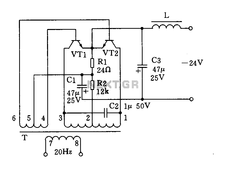
The circuit described is a 20Hz signal generator suitable for telephone ringing systems, alarm systems, and various other electronic applications. It consists of a transformer (T) and two transistors (VT1 and VT2), forming a push-pull oscillator. The two transistors...
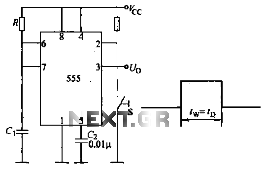
Introduction to the circuit schematic depicted in Figure 3-3. In this configuration, the 555 timer is utilized in a monostable mode, typically activated by a normally open push button switch. The circuit operates in an S-shaped state, where the...
This circuit is designed to detect microwave sources, such as microwave ovens, satellite communication devices, and mobile phones. It provides audio-visual indications upon detecting microwaves in the gigahertz band, which encompasses frequencies between 2 GHz and 300 GHz. Microwave...
There are two independent modeling light circuits for the P2000D, one for each of the two channels. The modeling light circuit is completely separate from the high voltage strobe circuitry, even featuring its own On/Off switch. Therefore, the functionality...
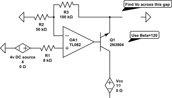
The voltage measured at 12V after the emitter is perplexing, especially when the output from the op-amp is +15V, suggesting a 3V drop across the transistor. This raises questions about the expected gain of 2, which would imply an...
This is a straightforward high-quality PLL FM transmitter with a typical output power of 5 W and a no-tune design. It features RDS/SCA input and audio/MPX input with optional pre-emphasis and can operate with or without a stereo encoder....