
Arduino Clock Based on PCF8563
.jpg)
The circuit involves several key components: an Arduino board, a PCF8563 RTC IC, an optional LCD display, and a power source. The PCF8563 communicates with the Arduino via I2C protocol, utilizing the SDA (data line) and SCL (clock line) pins for communication. The Arduino is programmed to read the time and date from the RTC and display it accordingly.
To set up the circuit, connect the PCF8563 to the Arduino as follows: connect the VCC pin of the RTC to the 5V pin on the Arduino, the GND pin to the ground, the SDA pin to the Arduino's A4 pin, and the SCL pin to the A5 pin. If an LCD is used, it can be connected using the appropriate pins, typically through a separate library that manages the display.
In the code, the Arduino initializes the RTC and sets the time and date if required. The user can input the desired values through the serial monitor. The program continuously reads the current time and date from the RTC and updates the LCD display and the serial monitor accordingly.
In addition to the basic functionality, the optional battery ensures that the RTC retains the time and date settings even when power is disconnected. This feature is critical for applications requiring accurate timekeeping over extended periods without power. When implementing this circuit, it is essential to ensure all connections are secure and that the RTC is properly configured in the code to function correctly.In this tutorial, the Arduino displays the time and date on a LCD (optional) and in the Arduino IDE serial monitor window. A PCF8563 real time clock (RTC) IC is used to generate the time and date. The time and date can be set using the Arduino serial monitor window. An optional battery can be used to back up the time and date settings in the real time clock chip so that the time and date are not lost if the Arduino power is unplugged.
Prerequisites Preferably you should follow all the be. 🔗 External reference
Related Circuits
This is the second part of the square root algorithm. It was developed during the final stages of finishing this website and reviewing this document for publication. While Part I focused on an empirical discovery for a sequential algorithm...
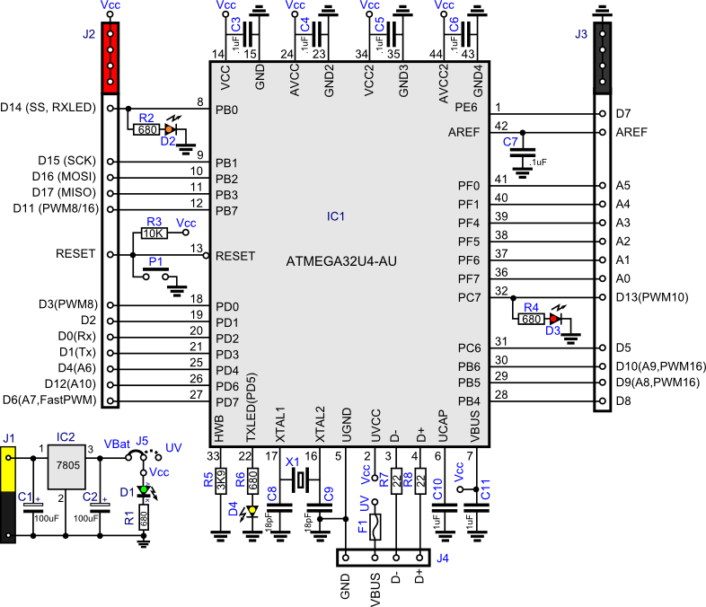
This project involves creating a clone of the Arduino Leonardo in a simplified manner. Consequently, the pin distribution does not conform to the standard Arduino layout. The Arduino Leonardo clone project focuses on replicating the functionality of the original Leonardo...

The following circuit illustrates a Bedside Lamp Timer Circuit Diagram. This circuit is based on the CD4060 integrated circuit. Features: An LED illuminates for approximately 25 seconds. The Bedside Lamp Timer Circuit utilizes the CD4060 IC, which is a versatile...
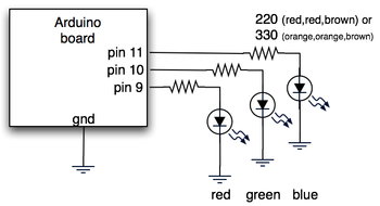
The hardware consists of an Arduino board connected via USB to a laptop, which recognizes the Arduino as a serial device. Three LEDs (red, green, blue) are mounted directly on the Arduino board using a prototyping shield. The schematic...
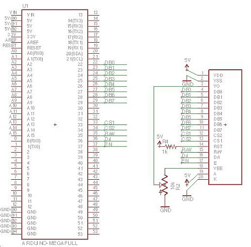
Displays are always beneficial. Until now, only 7-segment displays have been demonstrated for showing numbers using minimal resources. However, for displaying text or images, a simple LCD screen is required. There are basic LED screens available that operate on...
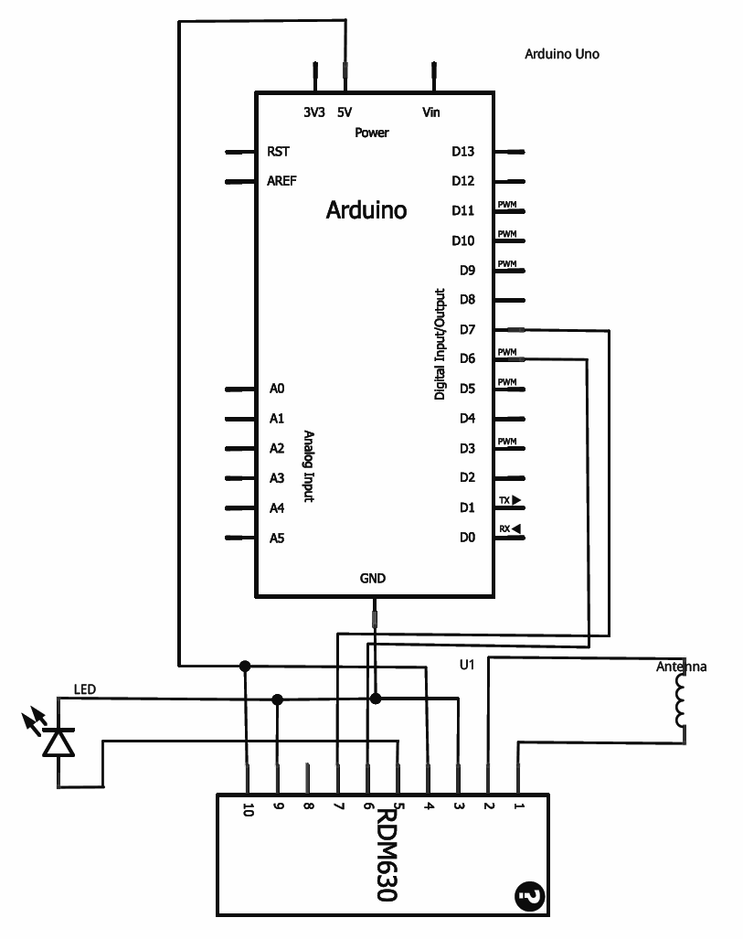
This tutorial provides guidance on integrating RFID functionality into a project using the RDM630 module from Seeed Studio, specifically its UART version. The module is mounted on a compact board with pre-soldered connectors, making it compatible with breadboards. To...