
Arduino Mega 2560
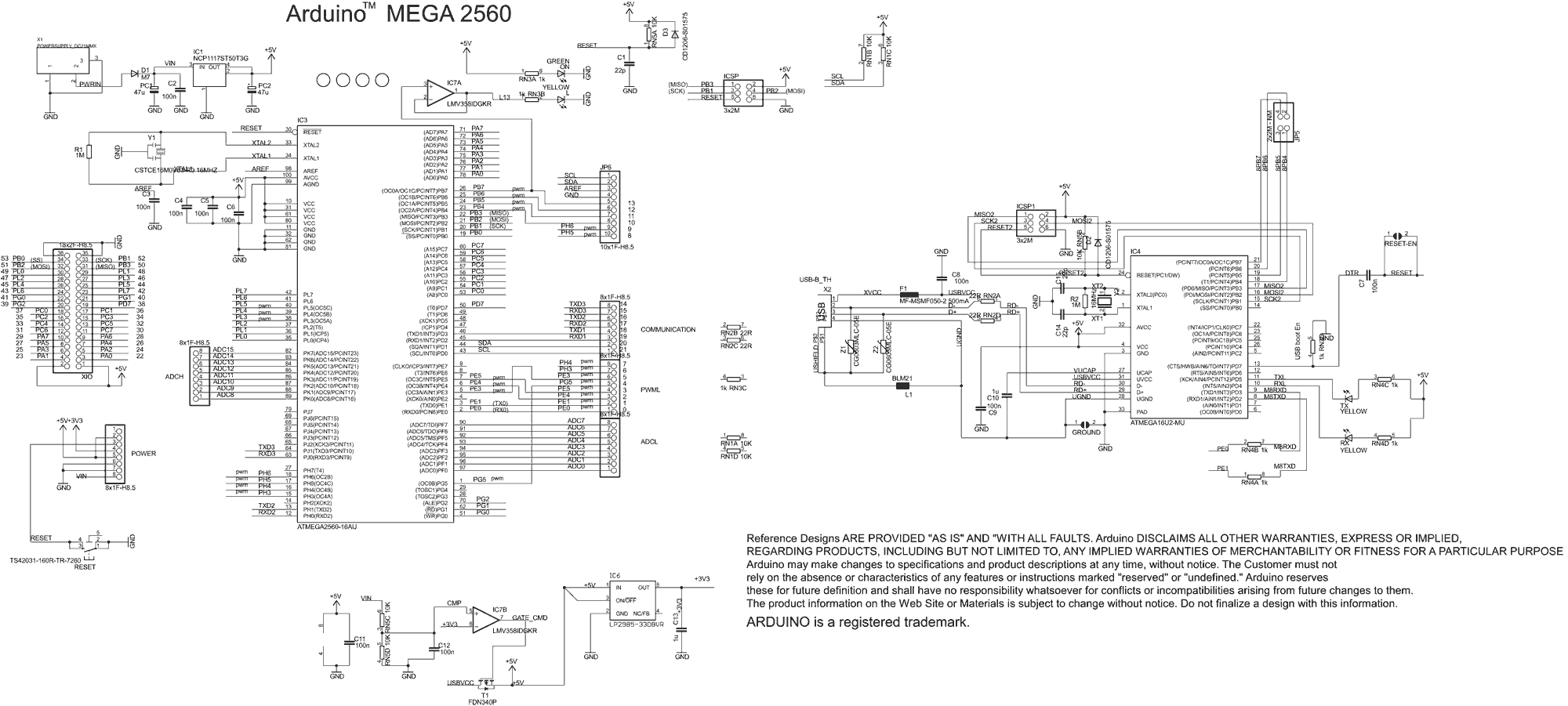
The Arduino Mega 2560 is a microcontroller board based on the ATmega2560. It features 54 digital input/output pins, 16 analog inputs, 4 UARTs (hardware serial ports), a 16 MHz crystal oscillator, a USB connection, a power jack, an ICSP header, and a reset button. The board is designed for projects that require more input/output pins and memory than the standard Arduino Uno.
The schematic of the Arduino Mega 2560 illustrates the connections and functionality of its components. The ATmega2560 microcontroller is at the core of the board, interfacing with various peripherals through its GPIO pins. The digital pins can be configured as either input or output, allowing for versatile applications such as controlling LEDs, motors, and sensors. The analog pins are used for reading varying voltage levels, making them suitable for interfacing with analog sensors.
Powering the Arduino Mega 2560 can be done through the USB port or an external power supply connected to the power jack. The board can operate within a voltage range of 7 to 12 volts, ensuring compatibility with various power sources. Additionally, the onboard voltage regulator ensures a stable 5V supply for the microcontroller and connected peripherals.
The Arduino Mega 2560 is compatible with the Arduino IDE, which provides a user-friendly environment for programming. Various libraries and examples are available to facilitate the development of complex projects, including robotics, data logging, and home automation systems. The extensive community support and documentation enhance the usability of the Arduino Mega 2560, making it an ideal choice for both beginners and experienced developers.Arduino Mega 2560 Board Tutorials Projects Drivers, Schematic and complete Information. 🔗 External reference
Related Circuits
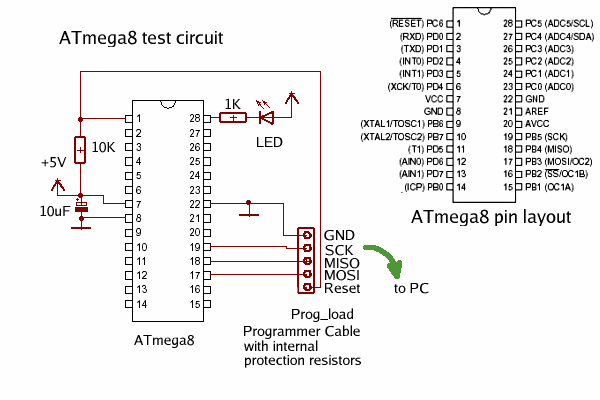
A programming jig has been constructed to eliminate the need for maintaining the circuit on a breadboard. Additional details and photographs are available on the Learning About the AVR Parallel Programmer page. The programming jig serves as a dedicated platform...
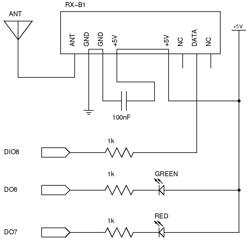
The documentation and code cleaning for the Jaycar Thermor/BIOS branded wireless weather station receiver has been completed. The code is based on the Practical Arduino weather station receiver project. The process involved analyzing the RF signal from the weather...
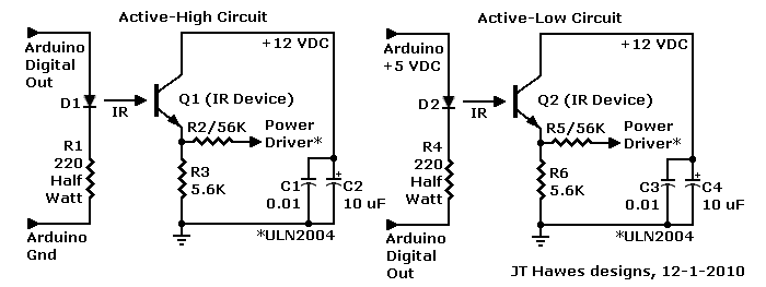
A Darlington transistor can enhance circuit performance, although it introduces slight complexity. The advantage of using a Darlington configuration lies in its capability to achieve low output impedance. The recommended component is the 2N6426 from Mouser, with alternatives such...
The objective of this post is to consolidate various robot designs and transform them into a new device featuring updated hardware and standardized software, specifically using Arduino, to enhance usability. These robots share three common elements: a mechanical structure,...
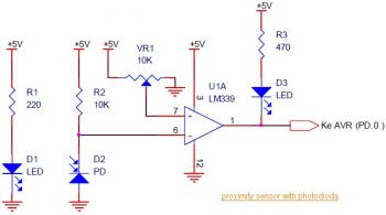
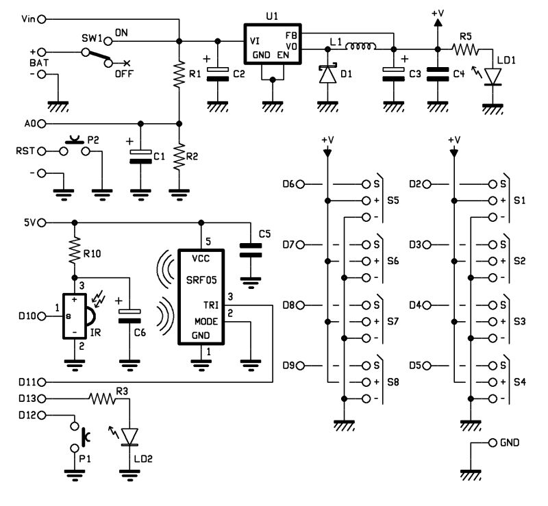
This circuit diagram illustrates a Line Follower / Line Tracker robot. The circuit is derived from tutorial documentation, which is available for download at the conclusion of this article. The line follower robot utilizes eight proximity sensor modules. Each...
The Arduino is a simple and accessible controller platform suitable for various projects. A few months ago, an Ethernet shield was purchased for it. The Arduino platform is widely recognized for its user-friendly interface and versatility, making it a popular...