
arduino power inverter
The Arduino microcontroller serves as a versatile platform for developing various power conversion circuits. These circuits can include DC-DC converters, AC-DC converters, and other forms of power management systems. The flexibility of the Arduino allows for easy integration with sensors and other components, enabling the design of circuits that can adapt to different input voltages and current requirements.
A typical DC-DC converter circuit might utilize a boost converter configuration, where the Arduino controls a switching element, such as a MOSFET, to increase the voltage from a lower level to a higher level. The circuit would include an inductor, diode, and output capacitor, with feedback mechanisms implemented through the Arduino's analog input pins to maintain the desired output voltage.
For AC-DC conversion, a rectifier circuit can be designed, utilizing the Arduino to monitor the output and adjust the duty cycle of the PWM signals. This could involve the use of a bridge rectifier followed by a smoothing capacitor to provide a stable DC output.
Additionally, power management circuits can be implemented to optimize battery usage or to manage power distribution in larger systems. The integration of the Arduino allows for programmable control, enabling the user to set thresholds for voltage and current, which can be critical in applications such as renewable energy systems or portable devices.
Overall, the use of an Arduino microcontroller in power conversion circuits enhances the capability to create adaptable and efficient power management solutions suitable for a wide range of applications.Build various power conversion circuits with Arduino microcontroller.. 🔗 External reference
Related Circuits
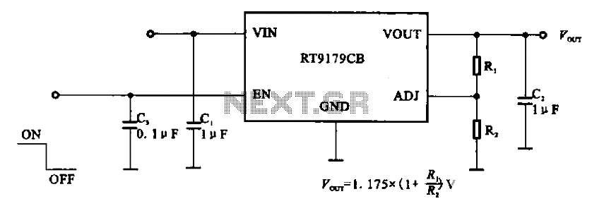
The RT9179CB is a power management chip utilized in power supply circuits. It serves as a linear regulator power management chip. This circuit is commonly employed in various products, such as computer motherboards, LCD monitors, and others. It is...
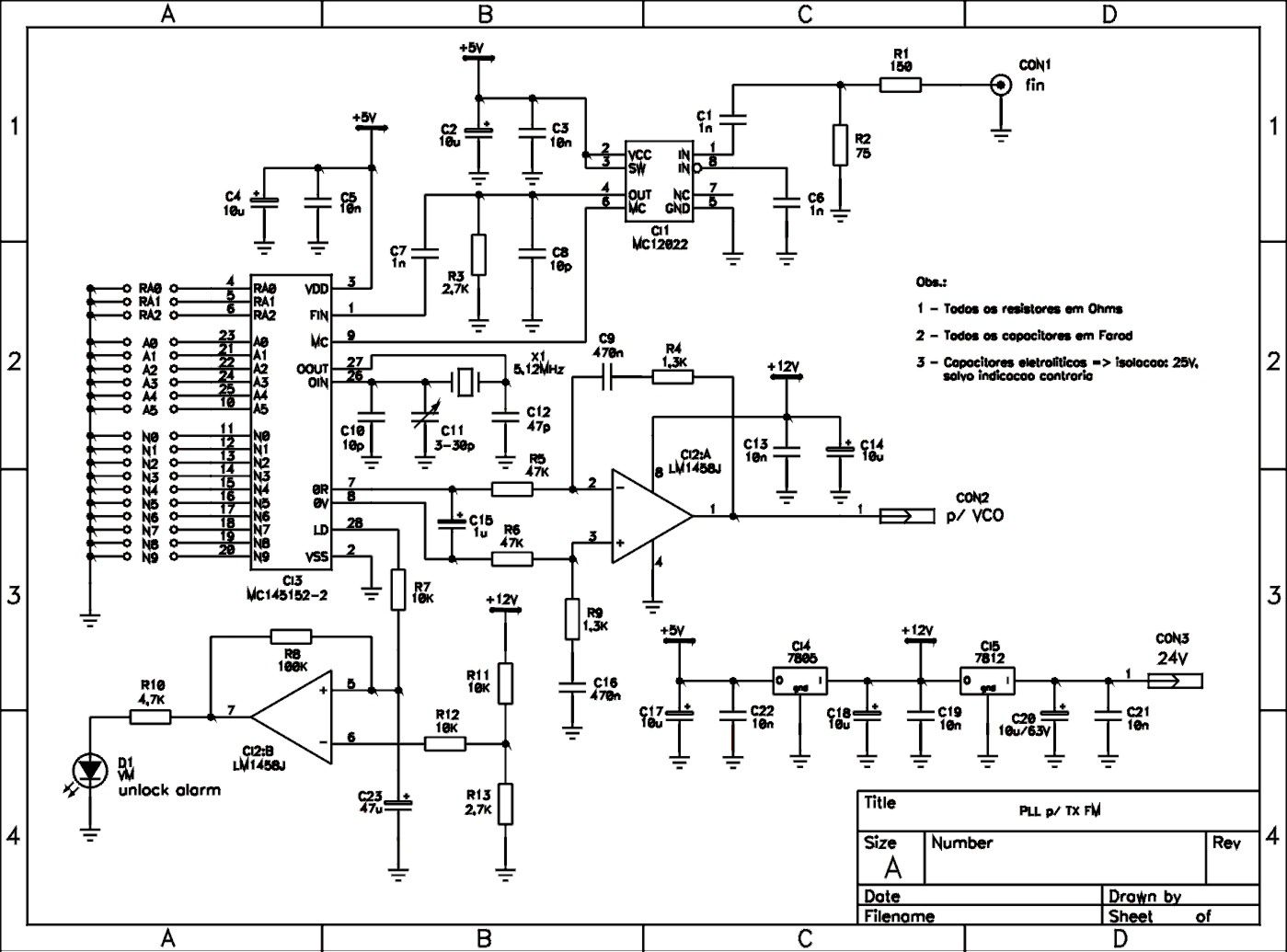
This is a schematic of a synthesized Phase-Locked Loop (PLL) for a low-power FM transmitter. It can also be utilized with other circuits, provided that the loop filter response, components, VCO tank circuit, and appropriate thumbswitch programming keys and...
This amplifier does not claim to be state of the art, and in fact the base design is now over 20 years old. It is a simple amp to build, uses commonly available parts and is stable and reliable....
This example demonstrates a technique for calibrating sensor input. The Arduino takes sensor readings for five seconds during startup and tracks the highest and lowest values obtained. These sensor readings during the first five seconds of the sketch execution...
A switch-mode power supply provides ±15V or ±12V at 0.5A output from a 4.5V to 12V input. The wide input voltage range allows flexibility to be powered from a regulated DC voltage. The switch-mode power supply (SMPS) described operates within...
Faulty readings from the DS18B20 temperature sensors used in tank thermometers were likely caused by the waterproofing method involving heat shrink and silicone. This situation provided an opportunity to enhance the code for better tolerance against erroneous readings. The...