
arduino Relay takes time to close
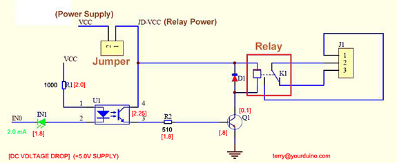
The circuit described involves controlling a relay using an Arduino-compatible microcontroller. The relay acts as an electronic switch, allowing the control of high-voltage devices with low-voltage signals from the Arduino. The connection of digital pin 2 to the IN0 terminal of the relay module indicates that this pin will provide the necessary signal to activate the relay. When the pin is set low, the relay is expected to close, thus completing the circuit for the connected load.
The low-voltage side of the relay module is powered directly from the Arduino's 5V and ground pins, ensuring that the control circuitry operates within safe voltage levels. The high-voltage side, designated as JD-VCC, is powered by a separate 5V 1A power adapter, which is also used to power the Arduino. The removal of the jumper connecting the high-voltage and low-voltage sides is crucial for preventing back-feed of voltage, which could damage the Arduino.
Concerns regarding the delay in relay activation and occasional failure to close suggest potential issues with the current transfer ratio (CTR) of the optoisolator used in the circuit. The optoisolator is responsible for transferring the control signal from the Arduino to the relay driver transistor (Q1). If the CTR is inadequate, the transistor may not fully saturate, leading to insufficient current flow to activate the relay.
The use of thin jumper wires for the power supply to the relay coils may also contribute to the problem if they introduce significant resistance, affecting the current available to the relay. Despite the relay's 80 mA current requirement, the wiring should be evaluated to ensure it can handle the necessary load without significant voltage drop.
To enhance performance, increasing the photodiode current through the optoisolator by adjusting the resistor values may improve the CTR and ensure reliable operation. Adding a 1kΩ resistor in parallel with the existing resistor (R1) can increase the current through the optoisolator, potentially leading to better saturation of Q1. However, care should be taken to maintain the photodiode current at levels that do not accelerate aging and degradation of the optoisolator.
In summary, addressing the relay activation delay and reliability issues involves examining the power supply connections, the wiring gauge, and optimizing the optoisolator's performance through circuit modifications. This approach ensures robust operation of the relay control system in conjunction with the Arduino.Control a relay from an Arduino compatible board. When I try to activate the relay from the Arduino it takes at least a second to switch closed and sometimes does not switch closed at all. Digital pin 2 of the Arduino is connected to IN0 of this circuit (bottom left). I set it low to switch on the relay. VCC and ground on the low-voltage side are connected to ground and 5V pins of the Arduino. The high-voltage side (JD-VCC) is connected to a 5V 1A power adapter which also powers the Arduino. The jumper on the top left of the circuit connecting the high-voltage and low-voltage sides has been removed. One reason I suspected is that I have connected the power supply to the relay coils by thin jumper wires.
But the specification says that the relay draws a current of 80 mA. So I was hoping that the wires would be good enough. Assuming your supply isn`t collapsing somehow, to me it`s most likely that the CTR of the opto isn`t sufficient to saturate Q1 and meet the pull-in voltage requirement of the relay: The vast majority of optoisolators that I know of only guarantee their CTR at 5mA current or higher. Even a high gain opto (100-300% CTR) will underperform at this current level. It`s quite possible that many optos in this application will tend towards higher CTR and work without circuit modification.
Also, some Q1s may have much higher $H_{FE}$ and handle the weak drive. I would consider soldering another 1k in parallel with the existing R1 and see if the relay performance improves. Most optoisolators can handle up to 50mA photodiode current; that being said, the diode current should be set to the lowest possible current that allows your application to operate robustly, since optoisolators do age (the CTR degrades over time: faster as the photodiode current increases).
🔗 External reference
Related Circuits
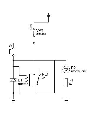
The circuit can also be triggered by logic ICs (TTL/CMOS) using the appropriate interfacing method. Another relay is typically used to serve as the trigger button when interfacing ICs with the latching relay circuit. The described circuit utilizes a latching...
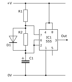
The following circuit illustrates a practical electronics astable circuit diagram based on the 555 Timer IC. This circuit produces a pulse frequency of approximately 2Hz with a very low mark-space ratio, making it suitable for various applications. The single...
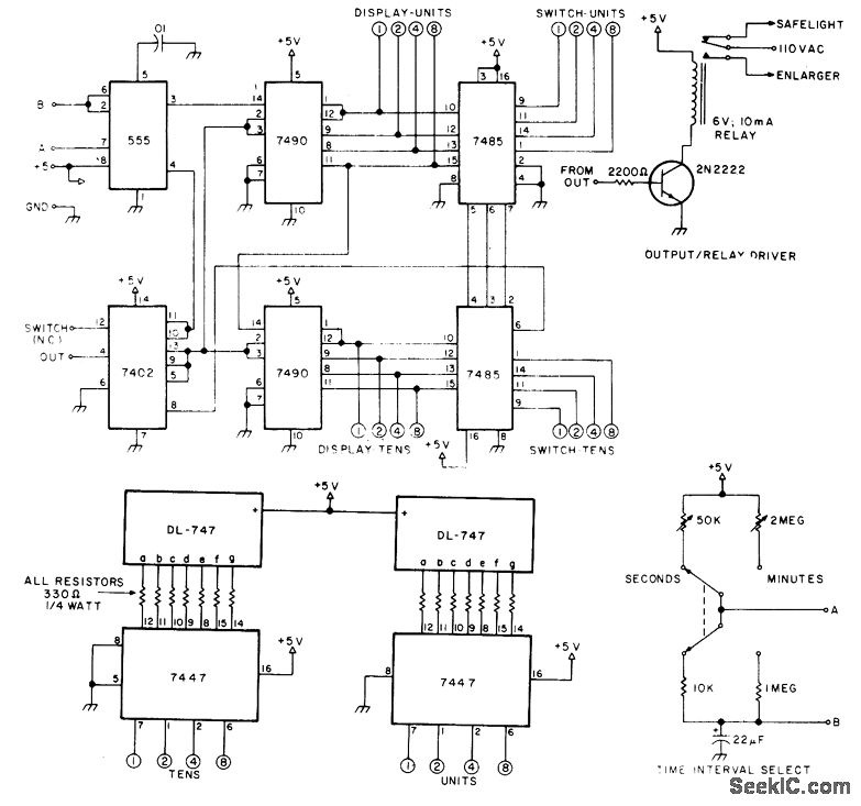
The circuit provides timing capabilities ranging from 1 second to 99 seconds and from 1 minute to 99 minutes, featuring a 2-digit LED indicator that displays the elapsed time. The desired timing interval is set using BCD thumbwheel switches....
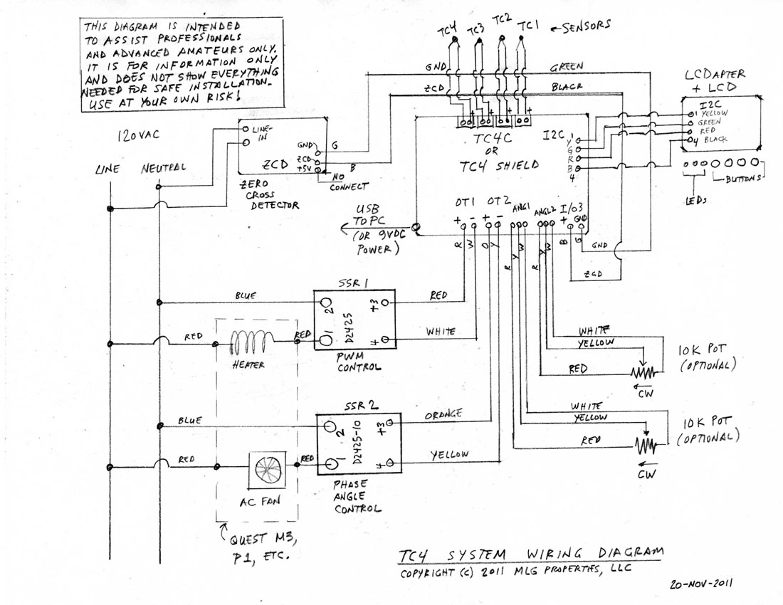
This is a complete standalone system compatible with Arduino Uno, which will be fully assembled, tested, and programmed prior to shipping. Users can select from various TC4 applications to be pre-programmed into the board. For those who wish to...
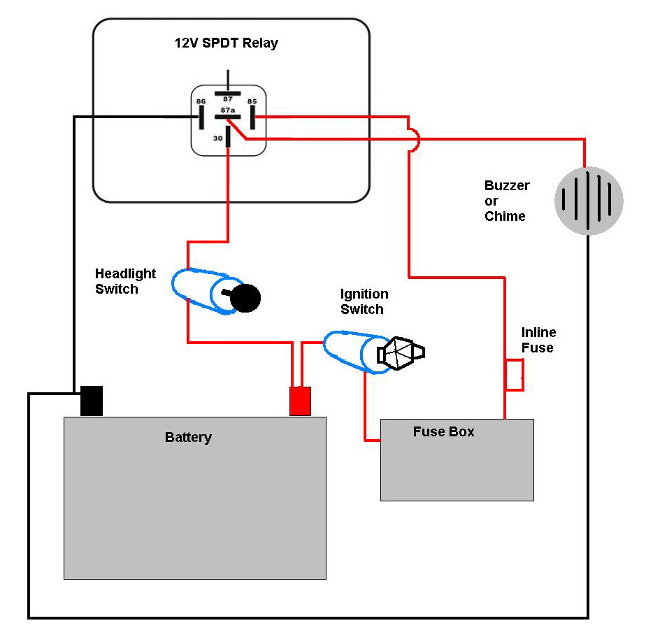
A bike equipped with a 35-watt HS1 bulb is being upgraded to a brighter headlight using an H4 60/65-watt xenon bulb. An expert recommended using relays due to the increased power requirements of the new bulb. Research conducted on...
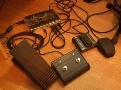
Build a Guitar Looper with an Arduino board. Here is how to produce a pedalboard for electric guitar. The idea is to connect pedals to the Arduino and to use them to control a software of sound processing in...
Warning: include(partials/cookie-banner.php): Failed to open stream: Permission denied in /var/www/html/nextgr/view-circuit.php on line 713
Warning: include(): Failed opening 'partials/cookie-banner.php' for inclusion (include_path='.:/usr/share/php') in /var/www/html/nextgr/view-circuit.php on line 713