
assembly language for wiper based 8051 microcontroller
The microcontroller-based water tank filler circuit is designed to automate the filling of water tanks while preventing overflow. The circuit typically utilizes a microcontroller, which serves as the central processing unit, to monitor water levels through sensors and control the operation of a pump.
The primary components of this circuit include:
1. **Microcontroller**: Acts as the brain of the system, processing inputs from the water level sensors and controlling the pump's operation based on predefined conditions.
2. **Water Level Sensors**: These sensors detect the water level within the tank. Common types include float switches, ultrasonic sensors, or capacitive sensors. The microcontroller interprets signals from these sensors to determine whether the tank is full or empty.
3. **Pump**: An electric pump is used to fill the tank with water. The microcontroller sends a signal to activate the pump when the water level falls below a certain threshold and deactivates it when the desired level is reached.
4. **Power Supply**: Provides the necessary voltage and current to the microcontroller and pump. Adequate power management is crucial to ensure reliable operation.
5. **Control Circuitry**: This may include relays or transistors that interface between the microcontroller and the pump, allowing the low-power microcontroller to control the higher-power pump.
6. **Programming Interface**: The microcontroller is programmed with specific algorithms to manage the filling process, handle sensor inputs, and ensure safety features are in place to prevent overflow.
In addition to the water tank filler circuit, the input data also references various applications and projects involving microcontrollers. These include interfacing projects with parallel ports, real-life applications of microcontrollers, and specific projects such as drip irrigation systems and pulse oximeter designs using PIC microcontrollers. Each of these applications leverages the unique capabilities of microcontrollers, such as their ability to process inputs, control outputs, and communicate with other devices, making them versatile tools in modern electronics.
The design of such systems often involves careful consideration of the microcontroller's architecture, programming techniques, and interfacing methods to ensure optimal performance and reliability.Microcontroller based old water tank fillercircuit diagram. difference between microprocessor and microcontrollerppt, parallel port interfacing projects with microcontroller, microcontroller use in real live, circuit diagram of avr microcontroller trainer, 8086 of microcontroller, microcontroller based drip irrigation systemcircuit, design of pulse oximeter with pic microcontroller, microcontroller projects using speed input of lm2907, ppt examplesof lab prepared by by assembly programming 8051 microcontroller codefree download, data transfer pic microcontroller using usb irda.. 🔗 External reference
Related Circuits
The original FLED-based SE uses a flashing LED to drive a type 1 solar engine (you'll note that it's just like the Zener-based SE, but with a FLED in the starring role). The good news is that all the...
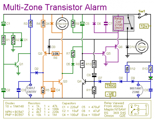
This transistor-based alarm system includes automatic exit and entry delays, a timed bell cut-off, and a system reset feature. In addition to the exit/entry zone, the basic alarm board is equipped with one instant zone, which is sufficient for...
The following circuit illustrates a Plant Moisture Meter Circuit Diagram. This circuit is based on the LM741 integrated circuit (IC). Features include a meter that indicates moisture levels. The Plant Moisture Meter Circuit utilizes the LM741 operational amplifier to measure...
The ASIC design focuses on a highly integrated, low-power solution with a short development cycle to complete an FPGA design aimed at achieving a robust background system, which holds significant practical relevance and broad market potential. The project utilizes...
This project provides a simple temperature-controlled fan. If the difference between the actual temperature and the user-defined temperature is significant, the fan will operate. The temperature-controlled fan circuit utilizes a temperature sensor, a microcontroller, and a fan motor to regulate...
To create a versatile and generic microcontroller board, the information provided thus far is sufficient. It covers the essential components needed to achieve this. The design of a microcontroller board requires careful consideration of various factors to ensure versatility and...