
Astable-multivibrator

The 4047 is configured as a free-running astable multivibrator (oscillator) circuit. This configuration offers three different outputs. The output pulses at the Q and Q output (pins 10 and 11, respectively) are the same as in the previous two circuits. The third output at pin 13 pulses twice as often as the outputs at pins 10 and 11. Therefore, the circuit can be used to simultaneously provide both positive and negative trigger signals since the Q and Q outputs are never in the same state, along with a clock frequency. Thus, the 4047 can replace both a simple oscillator (such as the 555) and a flip-flop in some applications.
The 4047 integrated circuit (IC) is a versatile component often utilized in various timing and oscillator applications. When configured as an astable multivibrator, the 4047 generates a continuous square wave output without requiring any external triggering. The frequency of oscillation is primarily determined by the external resistors and capacitors connected to the appropriate pins of the IC.
In this configuration, the outputs at pins 10 (Q) and 11 (Q) produce square waves that are 180 degrees out of phase with each other. This characteristic allows for the generation of complementary signals, which can be useful in applications requiring alternating signal states, such as in clock generation for digital circuits.
Pin 13 provides a unique output that pulses at twice the frequency of the Q and Q outputs. This feature can be advantageous in applications where a higher frequency signal is needed without the necessity of additional circuitry. The ability to obtain multiple frequencies from a single IC enhances the versatility of the 4047 in various electronic designs.
The circuit can be powered with a wide range of supply voltages, typically between 3V to 15V, making it suitable for battery-operated devices as well as more robust applications. Additionally, the 4047 can effectively replace traditional oscillators, such as the 555 timer, and flip-flops in certain applications, streamlining circuit designs and reducing component count.
To implement the 4047 in a practical application, careful selection of the timing components (resistors and capacitors) is crucial in determining the desired frequency and duty cycle. The circuit layout should ensure proper connections to power supply and output pins, with attention to minimizing noise and interference, which can affect the stability and accuracy of the output signals. Proper decoupling capacitors should also be used to maintain stable operation across varying load conditions.The 4047 is configured as a free-running, astable- multivibrator (oscillator) circuit. That configuration, offers three different outputs. The output pulses at the Q and Q output (pins 10 and 11, respectively) are the same as in the previous two circuits. The third output at pin 13 pulses twice as often as the outputs at 10 and 11. So, the circuit can be used to simultaneously provide both positive- and negative-trigger signals since the Q and Q output are never in the same state, and a clock frequency.
Thus, the 4047 can replace both a simple oscillator (the 555, for instance) and a flip-flop in some applications.
Related Circuits
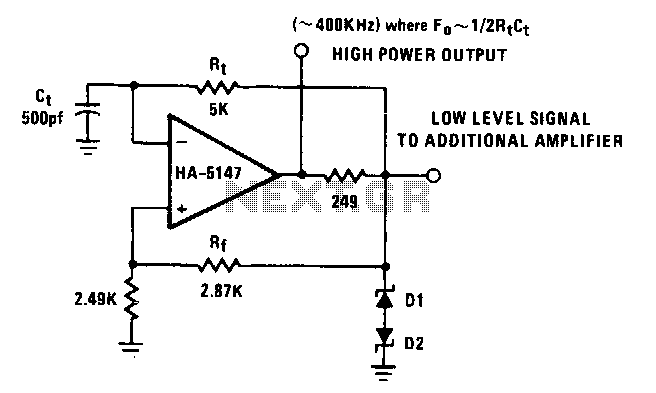
The power bandwidth of the HA-5147 extends the circuit's frequency range to approximately 500 kHz. Resistor R can be made adjustable to vary the frequency if desired. Any timing errors due to Vas or hu have been minimized by...
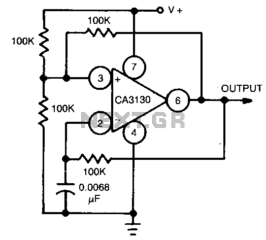
This circuit utilizes the CA3130 BiMOS operational amplifier, which operates at a frequency of 1 kHz. It features a rail-to-rail output swing, ensuring that the output can reach the supply voltage levels. The frequency of operation remains independent of...