
Astable Multivibrator Electronic
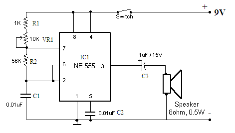
The described circuit functions either to trigger a connected device or to operate in a free-running mode, depending on the configuration of the components involved. The primary components include a battery for power supply, a charger for recharging the battery, and a battery connector that facilitates the connection between the battery and the rest of the circuit.
In addition, a capacitor is present, which may be utilized for filtering or energy storage purposes, ensuring stable operation of the circuit. The integrated circuit (IC) serves as the control unit, managing the triggering mechanism or the free-running operation.
Resistors VR1 (10K ohm), R1 (1K ohm), and R2 are integral to the circuit's operation. Resistor VR1 is likely a variable resistor, allowing for adjustable resistance, which can be used to fine-tune the circuit's response or timing characteristics. Resistor R1 may be involved in setting the biasing conditions for the IC, while R2 could play a role in current limiting or voltage division within the circuit.
Overall, this schematic provides a versatile platform for triggering devices or operating continuously, making it suitable for various applications in electronics, including timers, oscillators, or control systems. The precise arrangement and values of the components will determine the specific behavior and performance of the circuit.Function: to trigerred device or freerunning. Component: Battery, Charger, Battery Connector, Capacitor, IC, Resistor VR1-10K, Resistor R1-1K, Resistor R2 .. 🔗 External reference
Related Circuits
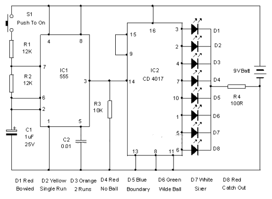
This electronic cricket device is a gift for children. This simple battery-powered circuit can be used to simulate a cricket match with friends. Each LED in the circuit represents various statuses of the cricket match, such as a six,...
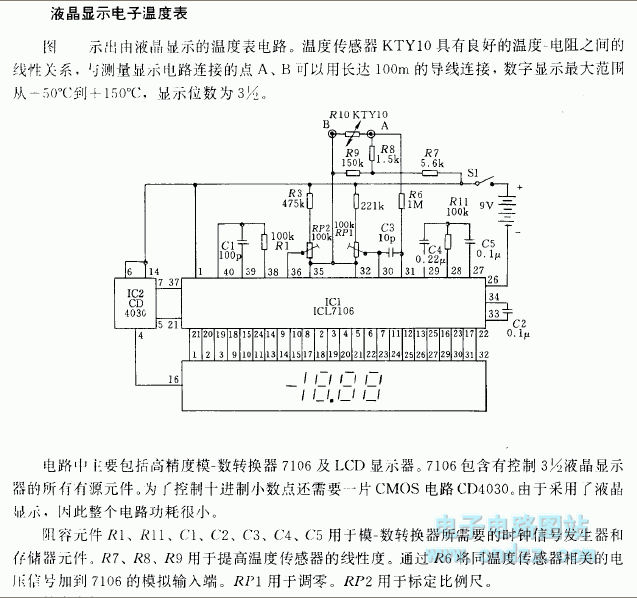
Related components PDF download: ICL7106CD4036. The LCD electronic thermometer circuit is illustrated. The temperature sensor KTY10 exhibits a strong linear relationship between temperature and resistance. Points A and B (Measurement display circuit) can be connected with a 100-meter wire....
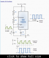
In the following astable multivibrator circuit, some sources state that the duty cycle is represented as d = (R1 + R2) / (R1 + 2 * R2), while other sources provide different information. The astable multivibrator circuit is a type...
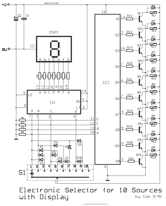
This is a circuit for alternative sources selection. It combines mechanical selection using a rotating switch S1, the electronic drive of the relays RL 1-10 and also the optical indication of the selection by the Display DSP1. The function...
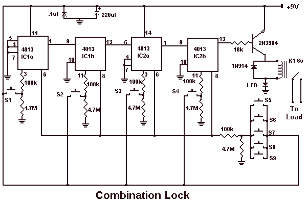
This circuit is very basic to build. To open a the lock which is connected to the K1 Load you must press each momentary switch in the correct sequence. The sequence used in this circuit is S1, S2, S3,...
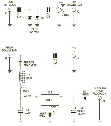
This wideband amplifier circuit is designed using the MAR-6 IC manufactured by Mini Circuits. The MAR-6 VHF-UHF wideband amplifier circuit provides a stable gain of at least 9 dB up to 2 GHz. Since the MAR-6 is designed to...
Warning: include(partials/cookie-banner.php): Failed to open stream: Permission denied in /var/www/html/nextgr/view-circuit.php on line 713
Warning: include(): Failed opening 'partials/cookie-banner.php' for inclusion (include_path='.:/usr/share/php') in /var/www/html/nextgr/view-circuit.php on line 713