
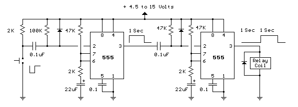
asymmetric timer
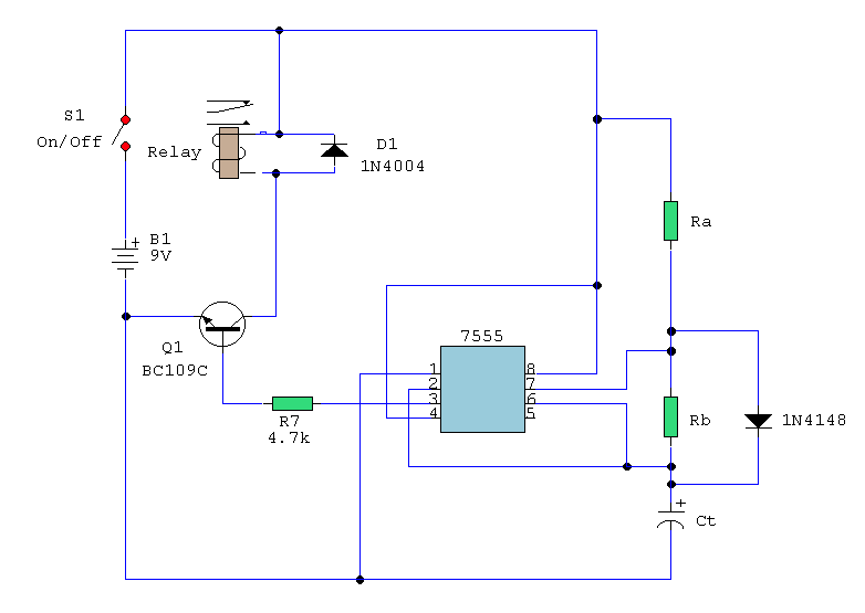
The astable multivibrator configuration using the 555 timer operates continuously, switching between its high and low states to create a square wave output. The timing cycle consists of two intervals: the high state duration (T(on)) and the low state duration (T(off)). The output frequency (f) of the oscillator can be calculated using the formula:
\[ f = \frac{1.44}{(Ra + 2Rb) \cdot Ct} \]
where Ra and Rb are the resistances in ohms, and Ct is the capacitance in farads. The high state duration (T(on)) can be determined by:
\[ T(on) = (Ra + Rb) \cdot Ct \]
and the low state duration (T(off)) is given by:
\[ T(off) = Rb \cdot Ct \]
In this configuration, when the output is high, capacitor Ct charges through resistor Ra and the diode, allowing for a faster charge time due to the diode's forward conduction. Once the voltage across Ct reaches approximately two-thirds of the supply voltage (Vcc), the 555 timer switches states, and the capacitor begins to discharge through resistor Rb into pin 7. The discharge continues until the voltage drops below one-third of Vcc, at which point the cycle repeats.
To ensure accurate timing, it is crucial to select appropriate values for resistors Ra and Rb, as well as the capacitor Ct. The choice of components will influence the frequency and duty cycle of the output waveform. Additionally, external factors such as temperature and component tolerances can affect the timing accuracy, particularly for T(on), which is approximated due to the diode's characteristics. In practical applications, this astable timer circuit can be utilized in various timing, pulse generation, and oscillation applications, making it a versatile component in electronic design.A simple astable timer made with the 555, the mark (on) and space (off) values may be setindependently. The timing chain consists of resistors Ra, Rb and capacitor Ct. The capacitor, Ct charges via Ra which is in series with the 1N4148 diode. The discharge path is via Rb intointo pin 7 of the IC. Both halves of the timing period can now be set inde pendently. Please note that the formula for T(on) ignores the series resistance and forward voltageof the 1N4148 and is therefore approximate, but T(off) is not affected by D1 and is thereforeprecise. 🔗 External reference
Related Circuits
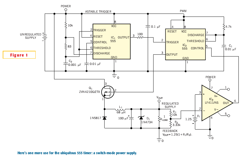
Most switch-mode power supplies utilize a PWM (pulse-width-modulated) output that is regulated through voltage feedback. A 555-timer IC can be used to generate PWM at a low cost. The circuit diagram illustrates how to convert a 555 PWM circuit...
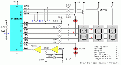
The clock timer utilizes a PIC16F628 microcontroller to display time in a 3.5-digit format and manage an external load. It features a calendar that accounts for leap years and optional daylight saving time adjustments. The timer output can be...
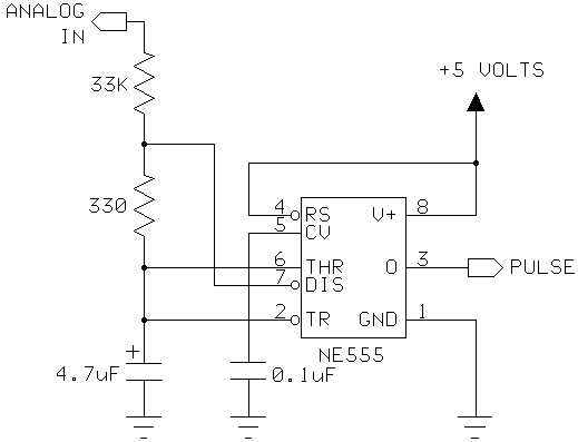
I had a Basic Stamp project that needed to measure a nominal 12 volt battery, and I wanted a simple solution. This is the simplest I could come up with. The 555 timer will put out positive pulses. The...
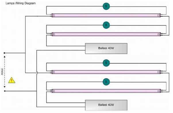
Four blacklight lamps, 15W each, emit radiation in the UVA region, with a peak around 350nm where the thin surface above the copper of the photosensitive board is sensitive. The lamps are taken by two and are connected in...
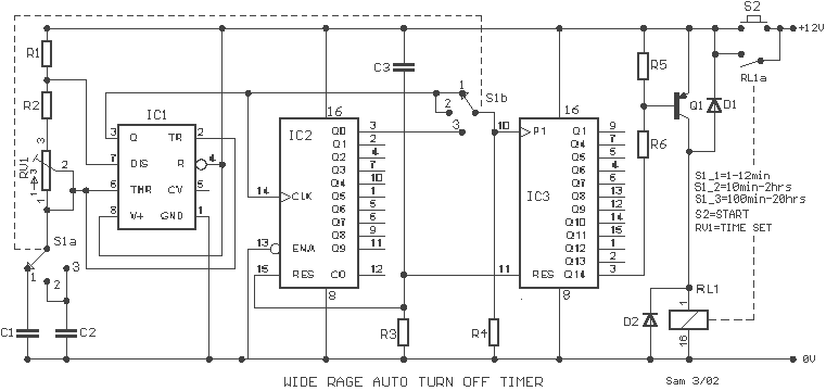
A wide range auto turn OFF timer covering 1 minute to 20 hours in three ranges with S1. As soon as power is applied to the circuit, the IC1 [555] starts to oscillate and feeds clock pulses to the...
This toggle circuit utilizes two 555 timers configured as inverters. Pins 2 and 6 serve as the threshold and trigger inputs for the first timer, while pin 5 provides the output. The output at pin 5 will consistently reflect...
Warning: include(partials/cookie-banner.php): Failed to open stream: Permission denied in /var/www/html/nextgr/view-circuit.php on line 713
Warning: include(): Failed opening 'partials/cookie-banner.php' for inclusion (include_path='.:/usr/share/php') in /var/www/html/nextgr/view-circuit.php on line 713