
Atari Joystick Wired Remote Control for Robots
The circuit employs a combination of discrete components to achieve joystick control for a robotic application. The FAN8200 dual motor driver chip is central to the design, providing efficient control over two motors while integrating essential features such as built-in protection diodes and pull-down resistors, which enhance reliability and reduce the need for additional components. The use of Schottky diodes, specifically the 1N5817, ensures that the circuit remains protected against reverse polarity connections, a common issue in battery-operated systems.
Capacitors C1 and C2 play a critical role in stabilizing the power supply to the motor driver, mitigating the effects of electrical noise and voltage spikes that could disrupt motor operation. This smoothing effect is particularly important during rapid changes in motor direction or speed, where inrush currents can lead to brief power fluctuations.
The circuit's design also includes a PNP transistor (Q1) that acts as a switch, allowing for efficient control of the motor's power without requiring high current to pass through the joystick wiring. This design choice not only enhances safety but also extends the lifespan of the joystick components, which might otherwise be subjected to excessive current loads.
The inclusion of resistors, such as R1, ensures that the transistor operates within safe parameters, providing a stable base current for reliable switching. The overall layout of the circuit emphasizes simplicity and functionality, making it an accessible option for hobbyists and engineers looking to implement joystick control in robotic applications without resorting to complex custom circuitry.
In summary, this circuit represents a balanced approach to joystick control, combining off-the-shelf components with thoughtful design considerations to create a robust and efficient solution for robotic motion control.The simplest solution for implementing joystick control for a robot would be to program the actions in software in a microcontroller. But, since many readers prefer off-the-shelf parts, this circuit is going to be made with diodes, resistors, transistors, and one FAN8200 motor driver chip.
The downside is that the circuit is more complex. D10: A S chottky (low voltage drop) 1N5817 diode to prevent the FAN8200 chip from being damaged if the batteries are installed backwards. Other types of diodes may be acceptable substitutes, but a Schottky diode will consume the least amount of power.
A diode is a one-way valve that blocks electricity from going the wrong direction. Electricity is allowed to go in the direction of the arrow, but not the other way. Thus, battery power is blocked if the batteries are installed backwards, but is permitted if installed correctly. C1 and C2: Capacitors store and release electricity locally to smooth out power glitches. This prevents errors in the FAN8200 motor driver chip due to spikes when switching the motors off and on.
IC1: Fairchild FAN8200 dual motor driver chip from Jameco Electronics or WrightHobbies. net. The chip can control two motors (hence the term dual ). It can operate from 2. 5V to 7V, which is why this circuit is specified for that range. The chip takes power, ground, and inputs and then outputs the power to the motors. You could build your own H-bridge, but that would make this circuit more complex. Ground=GND=a symbol with three stacked lines that looks like a shaded pyramid (see pin 14 and the bottom of the capacitors). All ground lines should be connected to the negative (-) side of the battery. It makes the circuit look less busy to use a symbol than to draw wires back to a battery. The advantages of the FAN 8200 chip are that it includes all of the parts to safely drive two small motors in coast, forward, and reverse mode.
The chip has built-in diodes and pull-down resistors. The chip is cheap (about $1). However, FAN 8200 motor driver chip is not very powerful or efficient. A home built h-bridge would likely deliver more power to the motors, but it would be more expensive, time consuming, and would require a lot more parts. Great! We`ve already identified many of the parts and their purposes. Let`s concentrate on the remaining parts: the diodes, resistors, and transistors on the left side of the circuit.
The easiest approach to running a motor when a switch is connected is shown on the left side of the above schematic. Power comes from the positive side of the battery, goes through the motor, through the fire button, to the negative side (ground) of the battery.
If the fire button is released, the switch is disconnected, and the power can`t go through the motor to reach the other side of the battery, so the motor won`t turn. If you`re trying to reduce parts, the left side of the above schematic is acceptable. However, it means that motor power has to go all the way through the joystick cable and back out to reach the battery.
The joystick wires and switch may not be rated for the amount of current your weapon motor needs. Also, the fire button may arc internally when released, reducing the lifespan of the button. Furthermore, if you decide to switch to a wireless setup (yes, they have wireless Atari joysticks!), it is unlikely that the left-side of the above schematic will work since the wireless joystick buttons will actually be emulated by a low-power chip. Q1: A PNP bipolar transistor such as a 2N2907A. When the base is connected to ground (because the fire button switch is pressed), the transistor turns on and supplies power to the motor.
When the base is disconnected (because the fire button is released), the transistor turns off and the motor stops turning. Motor power doesn`t go all the way through the joystick wires. It only goes through the transistor. R1: 1000 ohm resistor. A resistor is required at 🔗 External reference
Related Circuits
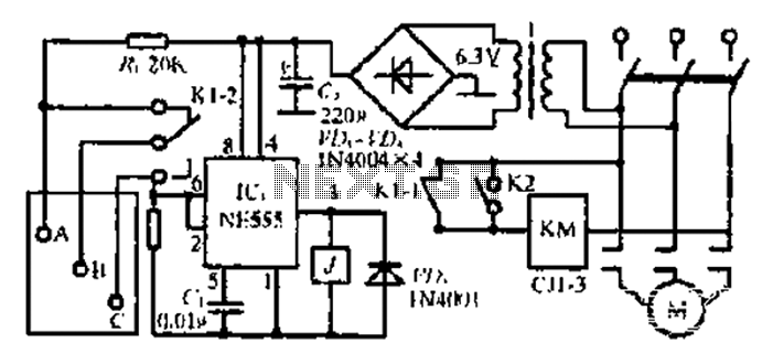
After the 3.40V power supply, the voltage is reduced to 6.3V through a full transition rectification using VDi and V sulfone. The C1 filter provides voltage stabilization after the caution circuit operates at the NE555 voltage level. When the...
A microphone cannot be directly connected to a power amplifier because the signal is too weak. Standard audio power amplifiers accept about 1 Vrms to provide a full output. To effectively interface a microphone with a power amplifier, an intermediary...
To achieve optimal performance as a low noise, high input impedance device, the preamplifier and tone control utilize JFET technology. The circuit is designed to minimize harmonic distortion levels. The use of Junction Field Effect Transistors (JFETs) in the preamplifier...
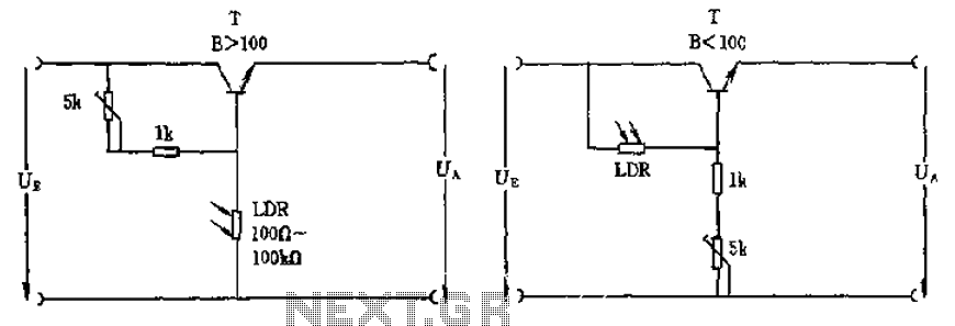
The circuit depicted involves a photoresistor (LDR) connected to a transistor, which operates at either a high or low level based on light conditions. The amplification factor of the transistor is 100, which is adequate for the application. The...
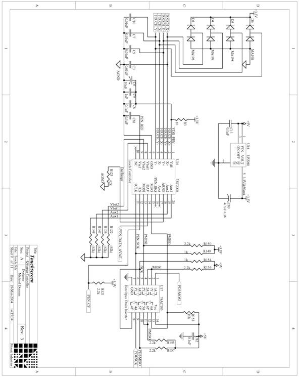
The following are detailed schematics for the QScreen Controller. The QScreen Controller integrates an embedded computer utilizing the 68HC11 microcontroller, along with a touch panel and an LCD (liquid crystal display) graphic user interface (GUI) that is well-suited for...
The motor winding is configured with delta transposition capacitance, designated as cl-C-3G. It operates as a DC LAN speed generator and is associated with a three-phase asynchronous motor, which is coaxially connected through a field winding powered by a...
Warning: include(partials/cookie-banner.php): Failed to open stream: Permission denied in /var/www/html/nextgr/view-circuit.php on line 713
Warning: include(): Failed opening 'partials/cookie-banner.php' for inclusion (include_path='.:/usr/share/php') in /var/www/html/nextgr/view-circuit.php on line 713