
ATmega8535 Line Follower Robot
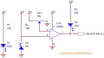
The Line Follower / Line Tracker robot circuit is designed to autonomously follow a path defined by a contrasting line on the ground. The circuit integrates eight proximity sensors that utilize photodiodes to detect light reflections. When the sensors identify the line, they send signals to the microcontroller, which processes the input and determines the appropriate motor actions to keep the robot aligned with the path.
The L298 motor driver serves as a critical component in this configuration, providing the necessary current to drive the motors effectively. With its ability to handle up to 2A for a single motor and 1A per motor for dual configurations, it ensures that the robot can perform efficiently without overheating or exceeding its operational limits. The L298 is particularly well-suited for small to medium-sized robotic applications, offering reliable performance.
The ATmega16 microcontroller serves as the brain of the robot, receiving input from the sensor modules and controlling the motor driver accordingly. The circuit design includes a mainboard schematic that integrates both the microcontroller and the motor driver, facilitating seamless communication between the components.
For educational purposes, the schematic diagrams provided in the tutorial are invaluable for understanding the underlying principles of line following robotics. The inclusion of an H-Bridge motor control circuit using TIP31 transistors allows for bidirectional motor control, enabling the robot to navigate turns and obstacles effectively.
In addition to the basic line-following functionality, the circuit can be enhanced with additional features such as sound effects or voice modulation, achieved through the integration of echo chamber circuits and robot voice effect circuits. These features can add an interactive element to the robot, making it more engaging for users.
Overall, this comprehensive circuit design not only demonstrates the fundamental principles of line-following robotics but also serves as a foundation for further exploration and experimentation in the field of robotics and automation.This is the circuit diagram of Line Follower / Line Tracker robot. The circuit taken from the tutorial documentation. You may download the full tutorial at the end of this article. The line follower robot use 8 pieces of proximity sensor module. The sensor module use photodioda for detecting the reclection of light from the line/floor. The motor d river L298 able to control the motor with current output up to 2A for single DC motor. For double DC motors, there should be up to 1A for each output channel. This motor driver is very good for small and medium DC motor. L298 is great motor driver for small and medium size or robot such as line follower robot and fire fighter robot. Download the complete line follower robot turotial which containing od schematic diagram, robot design and source code in PDF version (Indonesian language): Tags: atmega8535 circuit, line detector circuit, line follower atmega8535 circuit, motor driver l298 circuit, photodioda circuit, proximity circuit diagram, proximity sensor circuit, Here the complete electrical circuit diagram of line follower robot which built based on ATmega16.
There are three modules of line follower robot circuit that are sensor module, microcontroller module and DC motor module. IR sensor schematic diagram: Mainboard (microcontroller + DC motor driver schematic diagram): Download the document of ATmega16 line follower robot tutorial.
This is the circuit diagram of white line follower toy. The actuator of the toy is the DC motor. This circuit can be used fora toy car to follow a whiteline, this circuit also known as very simple robot: "line follower without microcontroller". The motor is either a3v type with gearing tosteer the car or. This is a DC motor controller circuit, built using transistor TIP31 based on H-Bridge concept. The switch S1 and S2 are normally open, push to close, press button switches. The LED function is to indicate the direction of motor rotation, you may use any common LED type. The TIP31 transistors capable to handle 3A. The following circuit is the combination of echo chamber circuit that will make the sound repeated, just like an echo sound when you speak in cave.
And the robot voice effect circuit that change the audio signal from input to become sound like a robot voice. To make the robot voice effect, there are some. This circuit is used to detect whether your phone line is active or not. Components List: R1, R2, R3 = 22M Ohms R4 = 2. 2M Ohms C1 = 0. 47uF/250V Mylar caps D1 = 1N914, NTE519, or other small signal diode Q1 = 2N3904, NTE123AP Q2 = 2N3906, NTE159 Q3 = IRF510, NTE2382, MosFet This kind of circuit.
This is a motor speed controller circuit diagram built based Maxim MAX4295. This with this circuit you will be able to control the speed of motor rotation. Resistor R1 biases the potentiometer to match the input range of U1. Full counter-clockwise rotation of the pot corresponds to maximum-speed reverse rotation of the motor. Mid-scale on. 🔗 External reference
Related Circuits
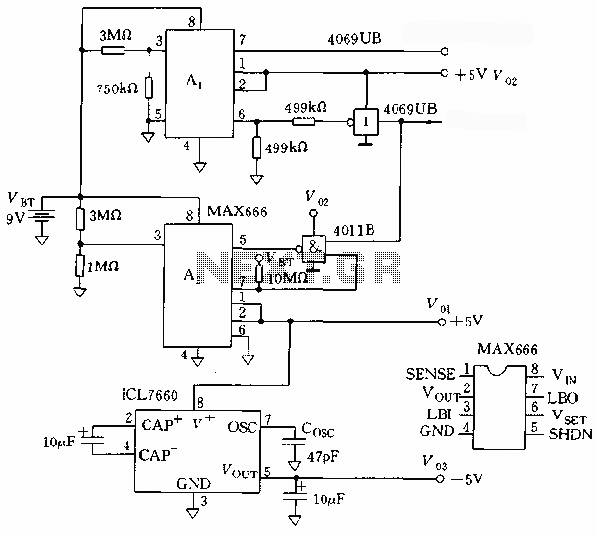
The microprocessor utilizes a linear regulator power circuit that is constructed using two MAX666 devices. The power supply for the CPU and A/D converter is connected to A2, while the RAM and real-time clock receive power from A1. The...
The Clarinet preamplifier is agile, detailed, and warm without being overly euphoric. It offers excellent sound staging, tonal balance, presence, and palpability. It surpasses other kit preamplifiers available and deserves serious consideration. Tube enthusiasts will appreciate this preamp, as...
Very little extra circuitry is needed to do both forward and backward walking sequences along with a few other tricks. The PIC16F818 has a lot of features that work well in this situation. As you can see from the...
If there is a suspicion that the broadband speed (DSL) is slower than expected, it may be due to incorrect polarity in the phone wall socket. A simple and inexpensive device can be built to determine if the wiring...
This simple circuit mixes two or more channels into one channel (eg. stereo into mono). The circuit can mix as many or as few channels as you like and consumes very little power. The mixer is shown with two...
That RF Amplifier is for boosting small fm transmitters and bugs. It uses two Philips 2N4427 and its power is about 1 Watt. At the output, you can drive any linear with BGY133 or BLY87 and so on. Its...