
Atmel AVR Microcontroller projects
The design of the speedometer/trip computer involves a straightforward yet effective method of measuring speed using a combination of a reed switch and a permanent magnet. The reed switch, when placed in proximity to the rotating magnet on the wheel, generates a pulse each time the wheel completes a revolution. This pulse is detected by the ATTiny2313 microcontroller, which is programmed to keep track of the time interval between successive pulses. By knowing the circumference of the wheel, the microcontroller can compute the speed of the cart in real-time, providing immediate feedback to the user.
The timer project utilizes a simple user interface with a single button, enhancing usability in a fast-paced environment. The choice of the PIC16F84A microcontroller allows for efficient power management, leveraging its sleep mode to minimize energy consumption. This feature is particularly advantageous in applications where battery life is critical.
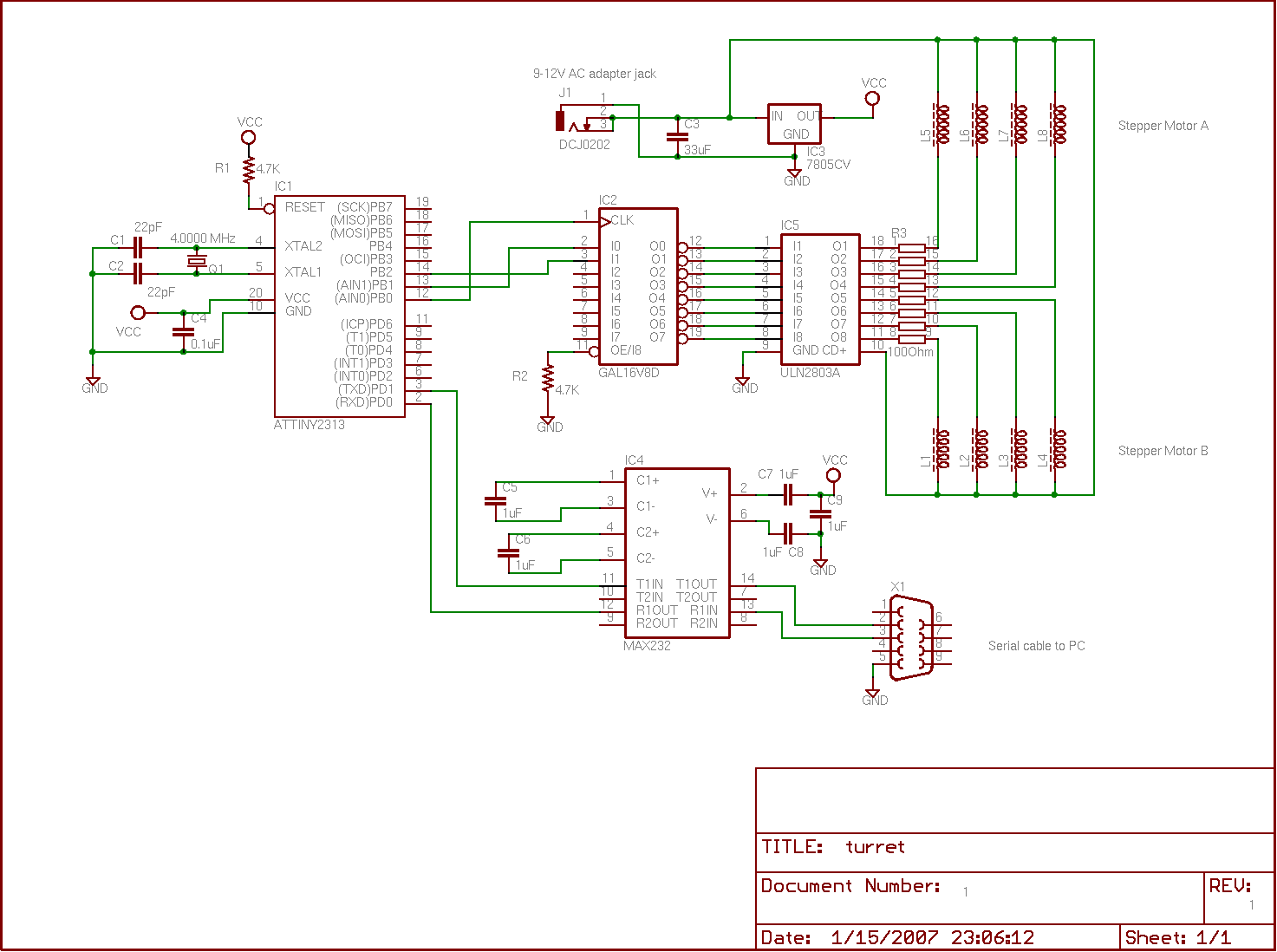
In the robotic turret project, the integration of stepper motors for precise control of movement demonstrates an effective application of microcontroller technology in robotics. The use of a GAL16V8 chip for the stepper motor controller allows for flexible programming and control of the motors while conserving the limited I/O resources of the ATTiny2313. The command interface via a MAX232 NIC enables seamless communication between the PC and the microcontroller, facilitating real-time adjustments to the turret's position based on user input.
Overall, these projects exemplify practical applications of microcontrollers in various electronic systems, showcasing the versatility and efficiency of modern electronic design in addressing specific user needs.Using an Atmel ATTiny2313 microcontroller and an HD44780-compatible character LCD display, along with a reed switch and some magnets, I was able to construct a tiny speedometer/trip computer for a soapbox derby cart. It measured the speed of the cart using a permanent magnet attached to the rear wheel`s rim, and a stationary reed switch attached t
o the soapbox derby cart. Every time the wheel revolved, the magnet would pass by the reed switch, thereby momentarily opening it. The microcontroller calculated the speed of the cart simply by dividing the circumference of the rear wheel by the period of the wheel`s revolution.
This project was motivated by a problem I heard about from a friend. At the Burger King where he works, employees should take no longer than three minutes to build a burger; however, at his Burger King, no way to measure your burger-building time was supplied. Initially, I suggested buying a watch or an egg-timer from the local dollar-store, but I was soon reminded of why that was not a great solution: it was too easy and rather boring.
The timer had to do one very simple thing: it had to count down from 3. 00 minutes to 0. 00 minutes and then beep. Consequently, I designed it to be very easy to operate. It had just one button - a very large, red one - that the user would press to turn on the device and start counting down from 3 minutes. Pressing the button while the count was already in progress would simply reset the count to 3 minutes.
When 3 minutes elapsed, the device beeps for 1 second, and then switches to a low-power mode. I used a 32. 768 kHz crystal and a PIC16F84A microcontroller as the heart of the device, taking advantage of the PIC`s low-power "sleep" mode so that one-button operation would be possible. There is no need for an "off" switch, because once it`s done timing, it just goes to "sleep", where it consumes very little energy until it is awakened by someone pressing its big red start button.
Essentially, I wanted to be able to control a little robotic arm / turret using a PC with a serial port. I thought this was a worthwhile project because I could later adapt it to aim a webcam, Nerf toy gun, or maybe even a felt pen so it could draw pictures.
One stepper motor rotated the base of the turret, while the other adjusted the turret`s pitch. I designed a stepper motor controller IC using CUPL (Univeral Compiler for Programmable Logic) and a GAL16V8 chip. This enabled an Atmel Attiny2313 MCU to control the two stepper motors using only three of its pins (one each for step, motor, and dir signals).
The Attiny2313 served as the "hub" that connected all the other components together by receiving commands from the PC via a MAX232NIC, performing basic calculations regarding the turret`s position and velocity, and then sending signals to the GAL16V8-based stepper-motor controller to drive the two stepper motors. In order to supply the voltages and currents necessary to drive each stepper motor, I used a Toshiba ULN2803A Darlington transistor array.
By clicking on the image to the right, you can view a video of the turret working. I wrote a program for my PC that would send the appropriate commands to the turret for it to follow a target on my computer screen. The result is quite entertaining. By clicking on the image below you can view a schematic I quickly put together of the circuit. It likely contains errors, but should at least provide a general idea of how the circuit is constructed.
This project was an ambitious project for my Engineering Science Capstone project (ENSC 440). The idea was to design an anti-lock braking system for a bicycle. In our small group of students, we divided up our work into various parts. One student focused mainly on the hydraulic actuators for the bicycle`s brakes; another student focussed mainly on the speed sensors for the bicycle`s wheels that would indicate a lock-up. I focussed on designing, buildin 🔗 External reference
Related Circuits
Security is a prime concern in our day-to-day life. Everyone wants to be as much secure as possible. An access control for doors forms a vital link in a security chain. The Microcontroller based Home Security System can be...
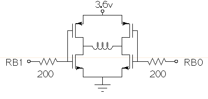
Drive a small (3.6V, <1A) brushed motor bidirectionally with a PIC microcontroller (MCU). The available space is extremely limited, so a single 3.6V power supply will be used for both the motor and the PIC, with minimal drive circuitry required. There is no dedicated motor driver IC that operates at this low voltage, making a discrete H-bridge the most suitable drive arrangement. The NXP PMV30UN and PMV32UP have been identified as suitable N-type and P-type drive MOSFETs. Since both the PIC and the motor share the same power supply, it is questioned whether it is possible to eliminate the usual driving circuitry for an H-bridge and connect the transistors directly to the MCU pins. Potential pitfalls of this approach should also be considered. To design a bidirectional motor drive circuit using a PIC microcontroller and a discrete H-bridge configuration, the following considerations must be taken into account. The H-bridge consists of four MOSFETs arranged in a configuration that allows current to flow through the motor in either direction, enabling bidirectional control. The NXP PMV30UN and PMV32UP MOSFETs are suitable candidates due to their low on-resistance and capability to operate at the required 3.6V supply voltage. The connections between the PIC MCU and the MOSFETs should be made with consideration of the gate drive requirements. Directly connecting the MOSFET gates to the MCU pins can be feasible, but it is essential to ensure that the MCU can provide sufficient gate drive voltage to fully turn on the MOSFETs. A typical threshold voltage for these MOSFETs is around 1V, so the output high level from the PIC should exceed this threshold to ensure efficient operation. It is also critical to incorporate pull-down resistors on the gate pins to prevent the MOSFETs from floating when the MCU is in a high-impedance state. This will help avoid unintended motor activation. Additionally, using gate resistors can help dampen any oscillations and limit inrush current during switching, which could potentially damage the MOSFETs or the MCU. Another consideration is the back EMF generated by the motor when it is switched off or when changing direction. This can induce voltage spikes that may damage the MCU or the MOSFETs. To mitigate this risk, flyback diodes should be placed in parallel with each MOSFET to provide a path for the back EMF, ensuring safe operation of the circuit. Thermal management is also a critical aspect of the design. Although the MOSFETs are rated for low on-resistance, continuous operation near their current limits can lead to significant heat generation. Adequate heat dissipation measures, such as heat sinks or thermal pads, should be considered. In summary, while it is possible to connect the MOSFETs directly to the MCU pins, careful attention must be given to gate drive requirements, protection against back EMF, and thermal management to ensure reliable and efficient operation of the bidirectional motor drive circuit.
This project is a microcontroller-based college automation system aimed at addressing the challenges faced in educational institutions. It replaces the conventional notice board with an automated device that allows users to both hear and read the information being announced...

This is a beta release schematic. Use at your own risk. The idea is to add this circuitry to a board that already has RAM at address 2000 and an 82C55 I/O chip to provide ports A, B, and...
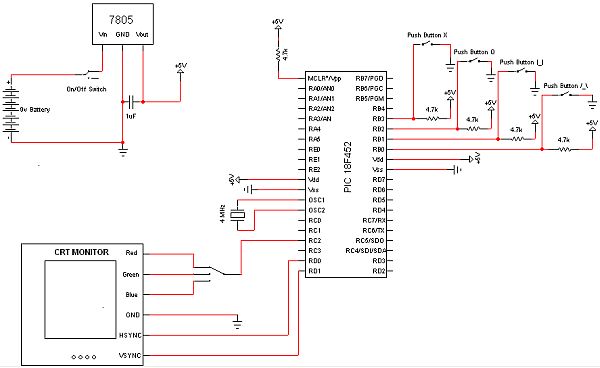
The objective of this project is to develop a device capable of outputting VGA signals to a CRT monitor to display figures, text, and characters. The project involves designing a circuit that generates standard VGA signals, which include separate horizontal...
Over 1400 top electronics projects and electronic circuits with photos, datasheets, and easy-to-read schematics, along with explanations of how they work and how to build them. The collection comprises a vast array of electronics projects suitable for enthusiasts and professionals...