
Audio amplifier with IC AN7522 AN7523 and TDA2616
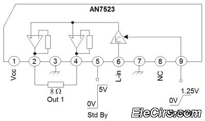
The BTL (Bridge Transformer Less) configuration is a significant advancement in audio amplification systems, particularly in applications where space and component count must be minimized. By employing a BTL design, the circuit achieves a more efficient power transfer to the load, which is often a speaker, without the need for traditional coupling components that can introduce distortion and reduce fidelity.
In a typical BTL setup, two amplifiers are used in a push-pull configuration to drive a load. Each amplifier outputs a signal that is 180 degrees out of phase with the other, effectively doubling the voltage across the load while maintaining a balanced output. This arrangement allows for higher output power levels and improved efficiency, as the amplifiers can directly drive the load without the need for transformers or capacitors that can limit frequency response and introduce phase shifts.
The absence of coupling capacitors is particularly beneficial in high-fidelity applications, as these components can filter out low-frequency signals and affect the overall sound quality. Additionally, the elimination of transformers reduces the size and weight of the overall system, making it more suitable for compact designs where space is at a premium.
Furthermore, BTL configurations can enhance thermal performance, as the heat generated by each amplifier can be more effectively managed when they are working together to drive the same load. This can lead to increased reliability and longevity of the components used in the circuit.
Overall, the BTL (Bridge Transformer Less) design represents a forward-thinking approach in the realm of audio amplification, providing clear advantages in terms of efficiency, size, and sound quality.Third series of the function with the same system, namely BTL (Bridge Transformer Less). By using such configuration we get several advantages, namely no use coupling capacitors or coupling transformers. 🔗 External reference
Related Circuits
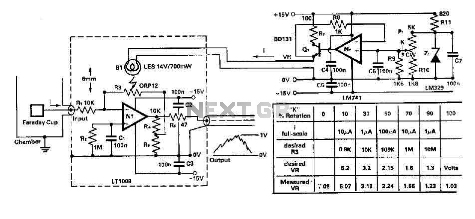
To amplify small current signals as an electron collector inside a vacuum chamber, it is advantageous for reasons related to noise and bandwidth to have a "head-amplifier" connected to the chamber. Operational amplifier 1 is a precision device featuring...
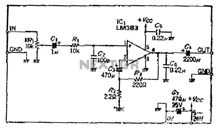
A closed-loop amplification circuit is designed to achieve a magnification of 100 times (40 dB). To ensure stable operation, particularly with high input signals, a variable resistor (VRi) is incorporated in the secondary circuit for attenuation. The feedback resistor...
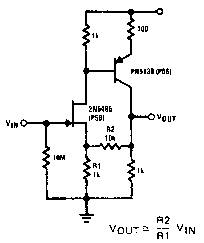
This compound series-feedback circuit provides high input impedance and stable wide-band gain for general-purpose video amplifier applications. The compound series-feedback circuit is designed to achieve high input impedance, which is essential for minimizing loading effects on the preceding stage of...
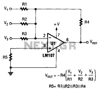
The output of Ul is the sum of Vv, multiplied by the ratio of Rx to Rv, RJRV, and respectively. Resistors R1, R2, and R3 are selected as required for individual gains. Additionally, R4 influences the gain of all...
Can simulate the character Mu symbol. A bone dish SET code is needed that effectively manages the decimal point. An inverted J is required to open its mouth. Left foot circuit diagram. The project involves designing a circuit that simulates...
This amplifier is designed to be as flexible as possible, with no bad habits. Indeed, it will operate stably with supply voltages as low as +/-5V (completely pointless, but interesting), all the way to the maximum supply voltage of...
Warning: include(partials/cookie-banner.php): Failed to open stream: Permission denied in /var/www/html/nextgr/view-circuit.php on line 713
Warning: include(): Failed opening 'partials/cookie-banner.php' for inclusion (include_path='.:/usr/share/php') in /var/www/html/nextgr/view-circuit.php on line 713