
audio amplifier with NE592

The NE592 broadband amplifier is a versatile component suitable for constructing a selective audio amplifier with high-performance characteristics. The circuit operates with dual supply voltages of +6 V and +12 V, enabling DC coupling between the product detector and the audio frequency (AF) amplifier. The differential inputs of the NE592 are set at a nominal DC level of approximately 4.5 V, facilitating optimal performance.
In the configuration, RF interference is mitigated through the use of two 47 nF capacitors, which filter out RF components before the AF signal is applied to the differential input of the NE592. Additionally, RF blocking between the outputs can be achieved with a single capacitor; however, it is crucial to maintain isolation between the outputs and ground to prevent distortion, particularly due to the amplifier's wide bandwidth.
The audio frequency stage of the amplifier is designed to provide a gain of 200 (46 dB) at a center frequency of 660 Hz, making it suitable for various audio applications. It is important to note that headphones with an impedance greater than 1 kOhm are recommended due to the relatively high output resistance of the NE592. The quiescent current of 18 mA is manageable in stationary applications, especially when powered by a compact AC-operated power supply.
For applications requiring lower power consumption, the use of dual op-amps such as the TL072 or TL082 is suggested, which can reduce the AF stage current consumption to 2 mA. These op-amps possess a lower output resistance, enabling them to effectively drive headphones with lower impedance, such as 2 x 32 ohms when connected in series with a 470-ohm resistor. Alternatively, the NE5532 can be utilized without the need for an additional resistor due to its inherently lower output impedance.
The circuit exhibits low distortion, excellent continuous wave (CW) selectivity, high gain, low noise, and a high output voltage. Despite its advantageous features, the circuit is not commonly implemented, possibly due to the requirement for adjusting resistor values R4 and R5 based on the quiescent current through IC1, which complicates mass production compared to single prototype devices.
The following components are specified for the circuit:
- R1: 10 kOhm
- R2: 8.2 kOhm
- R3: 1.8 kOhm
- R4, R5: 390 Ohm
- R6: 47 Ohm
- R7: 470 Ohm
- R8: 4.7 kOhm
- C1, C4: 47 uF, electrolytic capacitor
- C2: 10 uF
- C3: 2.2 uF
- C5: 150 pF
- C6, C7: 100 uF, electrolytic capacitor
- C8: 220 pF
- P1: 10 kOhm, linear potentiometer
- Dr1: 33 mH inductor
- VT1: 2N3906 transistor
- VT2: 2N3904 transistor
- IC1: NE592 broadband amplifier
This comprehensive description outlines the functionality and design considerations of the NE592-based audio amplifier circuit, emphasizing its capability to deliver high-quality audio amplification while addressing potential challenges in component selection and circuit implementation.The broadband amplifier NE592 can be used also for building a simple selective audio amplifier. By means of the +6 V and +12 V supply voltages a DC coupling between the product detector and the AF amplifier is possible. The DC level at the differential inputs is about 4,5 V. The mixer drives the differential input of the NE592 - after suppression of the RF proportions by two 47 nF capacitors - with the remaining AF signal.
RF blocking between the outputs is feasible with only one capacitor, but not between the single outputs and ground. But the latter is absolutly necessary due to the wide amplifier bandwidth. The AF stage offers a gain of 200 (46 dB) at 660 Hz center frequency. Headphones with Ri > 1 kOhm are mandatory due to the relatively high output resistance of the NE592 amp. 18 mA quietscent current isn't low, but it is insignificant in case of stationary operation and supply by a small ac-operated power supply.
You can reduce the AF stage current consumtion down to 2 mA when with a dual op amp TL072/082 instead of the NE592 broadband amp. These consumer op amps have a lower output resistance, so that they are able to drive 2 x 32 ohms headphones connected in series with a 470 ohms resistor.
When using a NE5532 no additional resistor is necessary, because the outputs have a less lower impedance. The transfer characteristic is the same as the one displayed for the first circuit (AF amp with NE592).
Low distortion, CW selectivity, high gain, low noise and a high output voltage are the features of the following circuit. This circuit is seldom used despite its good characteristics. The latter is perhaps because of the fact that one must try different resistance values for R4 and R5 depending upon the quiescent current through IC1.
This is ok for building a single device but not acceptable for a series product. Parts Value R1 10 kOhm R2 8,2 kOhm R3 1,8 kOhm R4, 5 390 Ohm R6 47 Ohm R7 470 Ohm R8 4,7 kOhm C1,4 47 uF, electrolytic cap. C2 10 uF C3 2,2 uF C5 150 pF C6,7 100 uF, electrolytic cap. C8 220 pF P1 10 kOhm, linear Dr1 33 mH VT1 2N3906 VT2 2N3904 IC1 NE592 🔗 External reference
Related Circuits
This is a 2x60W LM4780 Power Amplifier. The LM3886 was initially considered for this project due to its acclaim in previous designs. However, feedback suggested a need for a complete device. The LM3886 integrated circuit was difficult to source,...
It is quite easy to get a watt or more with very simple equipment, but to get more than 5 watts becomes a little more difficult. This article describes a 10 watt linear amplifier that is capable of delivering...
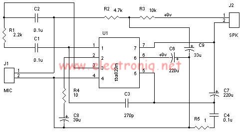
A very simple audio amplifier circuit can be designed using the TBA820M audio amplifier integrated circuit with just a few electronic components. This audio amplifier project features a high gain that allows for the detection of sounds underwater. The...
The objective of this design is to create a Combo amplifier that was popular during the 1960s and 1970s. It is particularly effective as a guitar amplifier but can also perform well with various electronic musical instruments or microphones....
The circuit utilizes two 2N3819 FETs configured in a cascode arrangement. The lower FET functions in common source mode, while the upper FET operates in common gate mode, achieving full high-frequency gain. The lower FET is tunable, enabling peak...
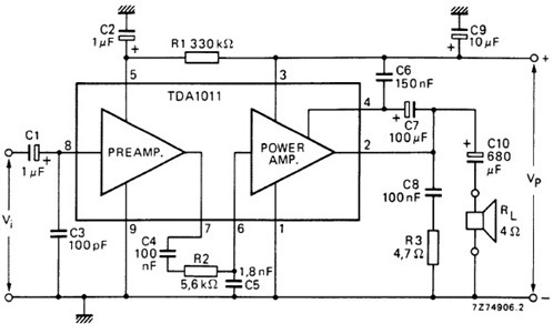
The following schematic illustrates the design of a 4 Watt Amplifier Circuit Diagram intended for portable radio applications, utilizing the TDA1011 integrated circuit from Philips Semiconductor. The 4 Watt Amplifier Circuit is designed to provide audio amplification in portable radio...