
Audio CD4001 based on Car Alarm Circuit
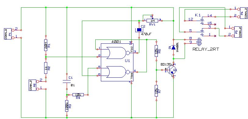
The alarm circuit utilizes the CD4001, which comprises four two-input NOR gates. The configuration of two NOR gates forms a bistable multivibrator, commonly referred to as a flip-flop. This arrangement allows the circuit to maintain its state until it receives an external reset signal, which in this case, is provided by the normally closed switch SW1. When SW1 is pressed, the state of the flip-flop changes, thus energizing the relay RL1.
The relay is essential for controlling higher power loads, as it acts as an electromechanical switch. The contacts of the relay can be configured to drive a siren and a light, providing both auditory and visual alerts when the alarm is triggered. The time constant for the circuit is determined by the values of R5 and C2, which can be adjusted to set the desired delay for the alarm activation.
In addition to the manual switch, integrating various sensors enhances the circuit's functionality. For example, a PIR motion sensor can detect movement within a specified range, while a smoke or gas detector can sense hazardous conditions, thereby activating the alarm without manual intervention. This versatility allows the circuit to be customized for different security needs, making it suitable for diverse applications such as residential security, vehicle protection, or industrial safety systems.
The design process includes simulation in Livewire to verify the circuit's behavior and performance before finalizing the layout in KiCad, ensuring that all components are correctly placed and connected for optimal operation. The printed circuit board (PCB) design will facilitate easy assembly and integration into the desired application, enhancing the circuit's reliability and effectiveness in providing security and alarm functions.This is a simple alarm circuit for a checkup with a 4001. It can be used to protect our home, motorcycle, car or any other application that comes to mind. In this circuit will be a computer simulation with Livewire and then design the printed circuit Kicad. SW1 is a normally closed switch when pressed triggers the flip-flop formed by the two NOR g ates of the CD4001 and remains there for a time determined by the time constant of R5-C2. This time it is keeping the relay RL1 and operated by its two contacts that investors control of two loads, for example, a siren and a light or any other that we connect to P3 and P4. We can replace the switch SW1 PIR motion sensor, an infrared barrier, a smoke detector, gas detector, a magnetic sensor, a panic button or other device to act as a closed switch and opened fire alarm.
🔗 External reference
Related Circuits
An increasing number of appliances draw a very small current from the power supply. If designing a mains-powered device, one can generally choose between a linear and a switch-mode power supply. However, when the appliance's total power consumption is...

A 555 four-base integrated circuit delay circuit is designed to facilitate a transition from high to low output. When the button SB is pressed, the output is set to high, and after a specified delay, the output transitions to...
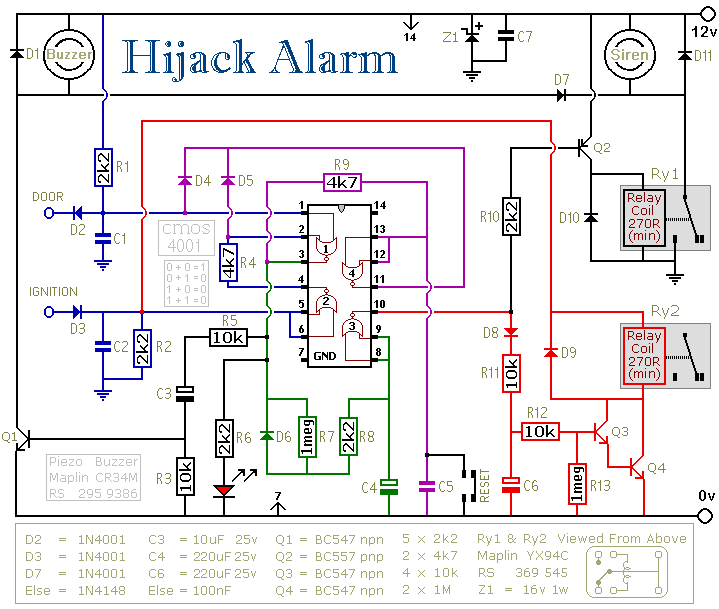
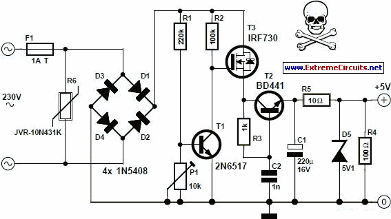
The first circuit is designed for situations where a hijacker forces the driver from the vehicle. If a door is opened while the ignition is switched on, the circuit will activate. After a few minutes delay, when the thief...
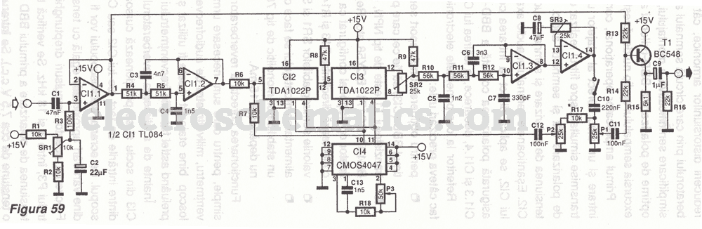
The first reverberator presented is based on the TDA1022, which is the most commonly used BBD (Bucket Brigade Device). Adjustments for proper functionality of the reverberator are required before connecting the power supply. The TDA1022 is a versatile BBD that...
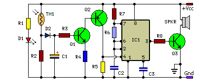
In this fire alarm circuit, a thermistor functions as the heat sensor. As the temperature rises, its resistance diminishes, and conversely, when the temperature falls, its resistance increases. At standard temperature, the resistance of the thermistor (TH1) is approximately...
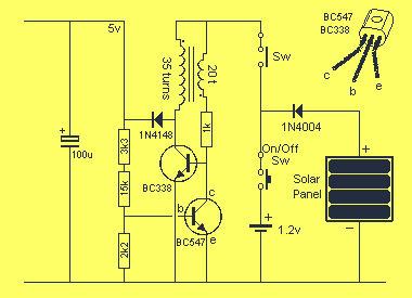
This project uses the 1.2v rechargeable battery and solar panel from a Solar Garden Light. These lights can be bought for less than $5.00 in most $2.00 shops or similar shops that sell general household items. We are also...
Warning: include(partials/cookie-banner.php): Failed to open stream: Permission denied in /var/www/html/nextgr/view-circuit.php on line 713
Warning: include(): Failed opening 'partials/cookie-banner.php' for inclusion (include_path='.:/usr/share/php') in /var/www/html/nextgr/view-circuit.php on line 713