
Audio Clipping Indicator
The circuit operates effectively by implementing a window comparator to monitor audio signals for clipping conditions, which is vital in audio applications where signal integrity is paramount. The window comparator's design allows for accurate detection of both the positive and negative peaks of the audio waveform, ensuring that any distortion caused by clipping is promptly indicated by the LED. This is particularly important in professional audio settings where maintaining sound quality is critical.
In practical applications, the circuit can be integrated into various audio equipment, enhancing its functionality without significant modifications. The ability to adjust the sensitivity through Trimmer R5 provides flexibility, making it suitable for different audio environments and requirements. The power supply versatility allows for adaptation to different systems, ensuring that the circuit can be used in a wide range of scenarios.
The inclusion of additional components such as diodes and capacitors for signal smoothing and delay aids in refining the detection process, allowing the circuit to react to transient signals effectively. The design considerations for current draw also ensure that the circuit remains efficient, making it suitable for long-term use in portable applications. Overall, this circuit serves as a valuable tool for audio professionals, helping to prevent distortion and maintain audio fidelity in various amplification scenarios.This circuit was intended to be used as a separate, portable unit, to signal by means of a LED when the output wave form of a particular audio stage is "clipping" i. e. is reaching the onset of its maximum permitted peak-to-peak voltage value before an overload is occurring.
This will help the operator in preventing severe, audible distortion to be generated through the audio equipment chain. This unit is particularly useful in signaling overload of the input stages in mixers, PA or musical instruments amplification chains, but is also suited to power amplifiers. A careful setting of Trimmer R5 will allow triggering of the LED with a wide range of peak-to-peak input voltages, in order to suit different requirements.
Unfortunately, an oscilloscope and a sine wave frequency generator are required to accurately setup this circuit. Obviously, the unit can be embedded into an existing mixer, preamp or power amplifier, and powered by the internal supply rails in the 9 - 30V range.
The power supply can also be obtained from higher voltage rails provided suitable R/C cells are inserted. SW1 and B1 must obviously be omitted. The heart of the circuit is a window comparator formed by two op-amps packaged into IC1. This technique allows to detect precisely and symmetrically either the positive or negative peak value reached by the monitored signal.
The op-amps outputs are mixed by D1 and D2, smoothed by C4, R7 and R8, and feed the LED driver Q1 with a positive pulse. C5 adds a small output delay in order to allow detection of very short peaks. With the values shown, the circuit can be easily set up to detect sine wave clipping from less than 1V to 30V peak-to-peak (i.
e. 15W into 8 Ohms). If you need to detect higher output peak-to-peak voltages, R1 value must be raised. On the contrary, if the circuit will be used to detect only very low peak-to-peak voltages, it is convenient to lower R1 value to, say, 220K omitting C2. In this way, the adjustment of R5 will be made easier. Using a TL062 chip at 9V supply, stand-by current drawing is about 1. 5mA and less than 10mA when the LED illuminates. With TL072 or TL082 chips, current drawing is about 4. 5mA and 13mA respectively. 🔗 External reference
Related Circuits
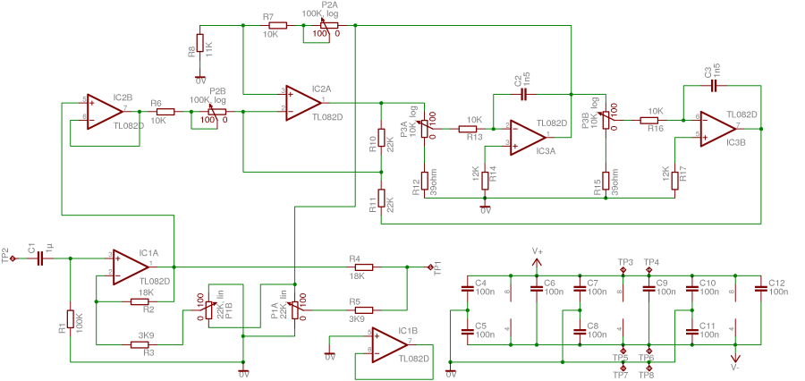
This project is based on the parametric equalizer proposed by Elektor in the late 1980s or early 1990s and later published in the book "Creations Electroniques" in 1993 (Publisher: Publitronic). Their design involved three stereo potentiometers per channel, resulting...
This project involved designing an audio amplifier capable of delivering substantial output power with a minimal number of components while maintaining quality. The power amplifier section consists of three transistors and a few resistors and capacitors configured in a...
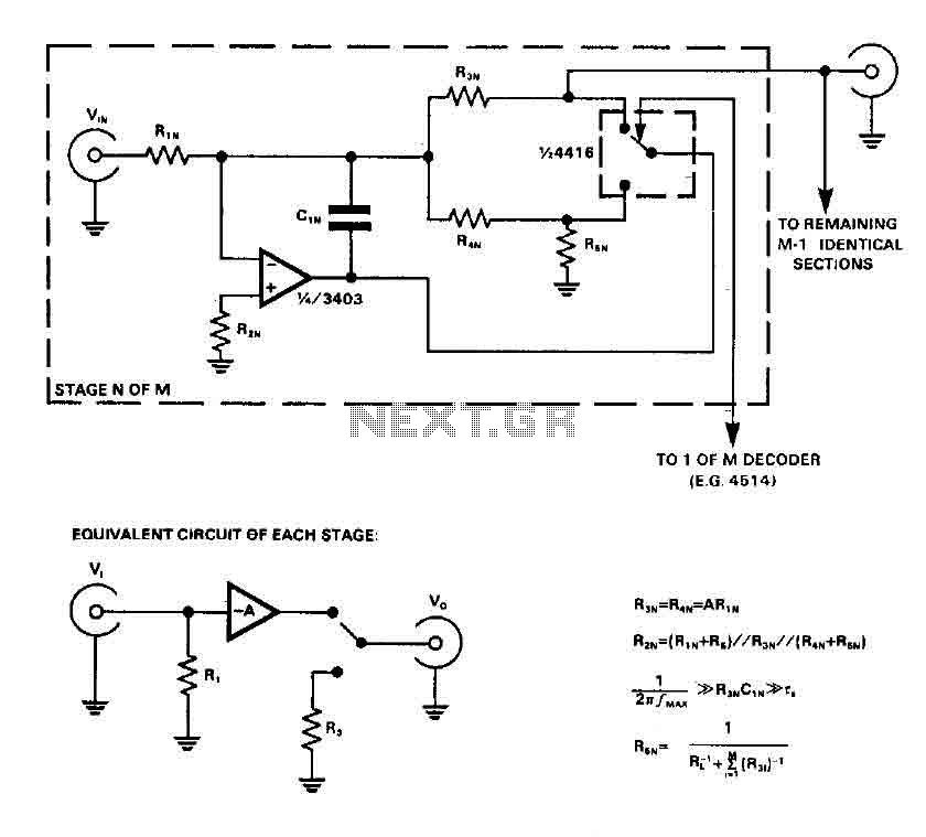
CMOS switches are utilized to select entries in audio circuits. While these switches can introduce unacceptable levels of distortion, incorporating them into the feedback network of an operational amplifier (op amp) can effectively minimize this distortion. The circuit employs...
The operating principle of the circuit is very simple. The first LED D1 is placed in series with the resistor R2 and diode D4. An only be lit this LED indicates that the battery is overcharged. For this reason,...
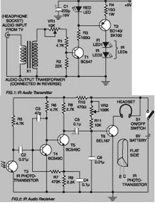
Using this low-cost project one can reproduce audio from TV without disturbing others. It does not use any wire connection between TV and headphones. In place of a pair of wires, it uses invisible infrared light to transmit audio...
This weblog discusses electronic circuit schematics, PCB design, DIY kits, and electronic project diagrams. The subject circuit is a quality preamplifier with a built-in USB DAC designed for the Leachamp power amplifier. The schematic is based on the PCM2902...