
Audio Detector switch
The circuit described is designed to detect specific audio signals, particularly those resembling a fire alarm, utilizing a piezo element from Radio Shack. The primary input stage employs a surplus electret microphone, which is powered through a 4.7kΩ load resistor. The microphone captures sound and converts it into an electrical signal, which is then coupled to the first operational amplifier (op-amp) stage via capacitor C4. This stage amplifies the signal by a factor of approximately 100, with the gain determined by the resistor ratio of R2 to R5.
Following the gain stage, the circuit incorporates a band-pass filter to isolate the desired frequency range. The filter's center frequency is adjustable and is defined by the values of capacitors C5 and C7, along with resistor R1. The quality factor (Q), which indicates the selectivity of the filter, is controlled by resistor R9. A value of R9 at 560Ω results in a relatively narrow bandwidth, enhancing the circuit's sensitivity to the target frequency.
The third stage further amplifies the filtered signal by about 30 times, providing a stronger output for the subsequent processing. The fourth stage includes a peak detector, which utilizes a diode to rectify the amplified signal and charge capacitor C9 to the peak voltage level. Resistor R14 is selected to control the discharge time of the capacitor, with a value of 10kΩ allowing for a discharge period of a few milliseconds.
For tuning the audio detector, it is recommended to connect an oscilloscope or digital voltmeter (DVM) to the output. While the signal is active, adjusting R1 should center the reading on the oscilloscope to optimize sensitivity. In cases where the input signal is excessively loud, repositioning the sound source may aid in achieving accurate tuning.
The output from the detector can recognize various sounds, including whistles and hand claps, but the output signal will not remain high for extended durations. To confirm a valid detection, it is necessary to sample the output and ensure it remains active for a minimum of 200-300 milliseconds. In practical applications, such as in the described Fire Fighting robot, the output functions as a "Push On, Push Off" switch, requiring five consecutive active samples at a 100ms interval (10Hz) to toggle the internal switch state.
Overall, the circuit's critical components are primarily those associated with the band-pass filter, specifically C5, C7, R1, and R9. The design is compatible with most +5V quad op-amps, and for rail-to-rail op-amps, adjustments to resistors R6 and R7 may be necessary to optimize the biasing within the operational voltage range.The following circuit can be used to detect those annoying piezo whistles that one can get from Radio Shack. For the Trinity Home Fire Fighting Contest, additional points accrue when the robot is started by a sound similar to a fire alarm.
The actual whistle is specified as a particular Radio Shack piezo element, but the following circuit should be tunable across a wide range of pitches. Gain Stage: The input is a standard surplus electrect microphone. Although I have not tried it, I suspect any condenser computer microphone will work just fine. The microphone is powered by the 4.7k load resistor. The resulting signal is coupled to the input stage via C4 and amplified by roughly 100x. The gain is set by the ratio of R2/R5. If not, the following images are the top and bottom view of the PCB. The bottom view is mirrored so it is correct when placed upon the bottom of the blank PCB. The images were intended to be printed out at 300dpi - that is why they are so big on your screen. So, copy them down, load them into your favorite image processor and print them out at 300dpi.. The board is ~1.2" x 1.5" - so it should be pretty tiny. The second stage is a band pass filter. The center frequency of the filter is set by C7, C5 and R1. The Q (or narrowness) of the filter is set by R9. With R9=560 the filter is pretty particular. The third stage is simply more gain, about 30x and the forth stage is a peak detector. The diode makes a rectifier that charges C9 to the peak value of the signal from the second gain stage. R14 is then chosen to determine the decay of the peak detector. With R14=10k the capacitor discharges in a couple milliseconds. To tune the audio detector, hook an oscilloscope, or DVM to the output of the circuit. With your signal on, adjust R1 to the center of the peak reading. If your signal is really loud it will be hard to determine the center frequency. In that case, move your signal across the room or tape the piezo element so it isn't so loud. The detector will detect random noises or whistles or hand claps, but, the output will not be held high for very long.
So, to determine when a valid signal has been detected, sample the output and verify that it has been active for more than 2-300ms. My Fire Fighting robot, Dilbert uses the detector as a "Push On, Push Off" switch; so the output is sampled every 100ms (10hz) and five consecutive active samples are required before changing the state of the internal switch.
There is nothing critical in the circuit except for the band pass components, C5, C7, R1 and R9. Most +5v quad op amps should work fine and if you use an op amp that works rail-to-rail, modify R6 and R7 to bias the amps more in the center of the voltage range. 🔗 External reference
Related Circuits

This audio processor circuit utilizes the SSM2045 integrated circuit (IC), specifically designed for electronic music applications, alongside the 741 operational amplifier (op-amp) IC. The audio processor circuit is centered around the SSM2045, which is renowned for its ability to provide...

This circuit can be directly connected to CD players, tuners, and tape recorders. It requires the addition of a 10K logarithmic potentiometer (dual gang for stereo) and a switch to accommodate various sources. Proper grounding is crucial to eliminate...
The standard Class AB audio power amplifier allows for direct coupling of the amplifier's output to speakers. This is beneficial as it eliminates capacitors or transformers that could compromise sound quality. The speakers are connected directly to the amplifying...
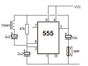
This metal detector electronic project schematic circuit is designed using a simple 555 timer integrated circuit. The schematic circuit requires a few external electronic components. The metal detector circuit utilizes the 555 timer IC in astable mode to generate a...
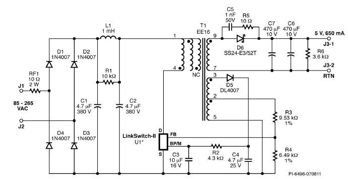
A simple 3.25W constant voltage/constant current (CV/CC) charger can be designed using the LinKSwitch family IC manufactured by Power Integrations. This electronic circuit project is intended to provide a 5-volt output with a maximum current of 650mA. The 3.25W...
This circuit is designed to indicate when room noise exceeds a predetermined threshold, utilizing a flashing LED to signal this condition. Three fixed noise levels are selectable: 50 dB, 70 dB, and 85 dB. The circuit employs two operational...
Warning: include(partials/cookie-banner.php): Failed to open stream: Permission denied in /var/www/html/nextgr/view-circuit.php on line 713
Warning: include(): Failed opening 'partials/cookie-banner.php' for inclusion (include_path='.:/usr/share/php') in /var/www/html/nextgr/view-circuit.php on line 713