
Audio Equalizer Circuits
The audio equalizer circuits described utilize operational amplifiers configured in a non-inverting amplifier topology, allowing for effective manipulation of audio signals. The choice of the LM741 operational amplifier serves as a versatile option, but designers may choose other amplifiers based on availability or specific performance characteristics. Each circuit's gain is carefully controlled, ensuring that the audio signal can be adjusted without introducing unwanted distortion.
The high-pass and low-pass configurations enable selective frequency management, essential for tailoring audio output to suit various acoustic environments or listener preferences. The high-pass Shelving Equalizer allows frequencies above a defined threshold to pass through unaffected, while attenuating lower frequencies, thus enhancing clarity and definition in the higher frequency range. Conversely, the low-pass Shelving Equalizer permits lower frequencies to pass while cutting higher frequencies, ideal for achieving a warmer sound profile.
The equations governing the frequency response of these equalizers highlight the importance of component selection, specifically the resistors and capacitors, in determining the cut-off frequency. By adjusting these values, designers can customize the performance of the equalizer to meet specific audio requirements. The use of a linear potentiometer for control provides precise adjustment capabilities, allowing for fine-tuning of the equalization settings, which is critical in professional audio applications.
Overall, these audio equalizer circuits represent a fundamental aspect of sound engineering, providing essential tools for audio manipulation and enhancement. The combination of operational amplifiers, carefully chosen passive components, and user-friendly controls results in a versatile and effective solution for achieving desired audio characteristics.This discussion continues on from the audio tone control topic, which introduced both passive and active tone controls. The follow on topics might be a 2-Band Active Tone Control, or the 3-Band Active Tone Control. An audio equalizer is used to adjust the amplitude of one or more frequency bands. The actual circuit adds equalization just as the tone controls did. The circuits are similar and use the same terms to indicate an amplification [boost] or attenuation [cut]. In fact there isn`t much difference between the two classes of circuits. Both of the circuits below indicate that they use a LM741 operational amplifier, but like all of these Op-Amp circuits any amplifier could be used instead of the 741.
The LM741 is just used to indicate that any general purpose operational amplifier might be used. In addition, no pin numbers are provided in the circuit diagrams so a single, dual or quad package Op-Amp could be used. Two operational amplifier circuit schematics are provided below. Both circuits are based on a non-inverting amplifier design. The LM741 [uA741] are configured as a unity gain amplifier, as Rf and Ri are shown as the same value.
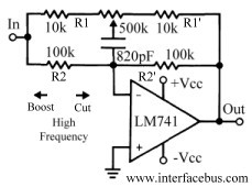
The gain of an inverting amplifier is Rf/Ri, or in this case R2`/R2 [ignoring the other passive components for the moment]. A Shelving Equalizer gets its name from the frequency response curve the circuit achieves. The characteristic curves resemble stacked shelves. There are two types; a high-pass Shelving Equalizer (which passes all frequencies above a certain frequency), and a low-pass Shelving Equalizer (which passes all frequencies below a certain frequency).
Both low and high pass equalizers are shown below. The first circuit uses a component placement that configures it as a high frequency equalizer. The equalizer is configured to pass all signals with out adding or reducing gain up to a particular frequency. The default gain of the amplifier is set at unity gain (1). The frequency at which the equalizer with either add gain [Boost] to the signal, or attenuation [cut] to the signal is determined by the following equation: 1 / (2 * p * R2 * C1).
The values called out in the equation set the frequency at 2kHz. This second circuit operates as the first, but at the opposite end of the frequency range. The circuit will pass all low frequencies up to a cut-off frequency (basically a low-pass filter). The equation that calculates the cut-off frequency is the same as before; 1 / (2 * p * R2 * C1). The component values used in the circuit will produce a cut-off frequency of 200Hz. A standard linear potentiometer should be used to control the equalizer. This differs from other audio controls such as a volume control which would use an audio taper which is logarithmic; however it`s the same style adjustable resistor that would be used as a bass or treble control. Normally when used on a front panel the potentiometer has a linear control, that is it moves up and back in a straight line, not left or right in a circular movement.
The linear movement of the control should not be confused with the linear value change of a taper. The resistor value ratio should be kept constant: The amount of change [boost or cut] is determined by the ratio of input and feedback resistance; R2, R3 / R1, R2. 🔗 External reference
Related Circuits
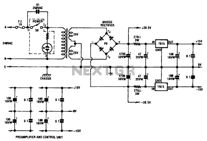
A dual audio amplifier that delivers 50 W per channel is illustrated in the schematic. It features a preamplifier and tone controls, as well as a headphone amplifier. The circuit also shows a power supply providing 38.5 V and...
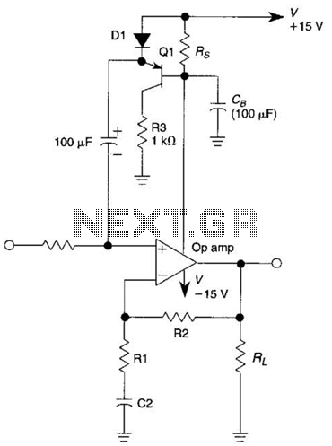
This circuit is an Automatic Gain Control (AGC) system designed for audio-frequency signals. AGC systems typically consist of three main components: an amplifier, a rectifier, and a controlled impedance. In this particular circuit, the functions of both the amplifier...
This preamplifier is designed for low-resistance sources such as moving coil heads (MC). The circuit employs three parallel double transistors, SSM2220 or MAT03, which form a differential amplifier that minimizes noise. When connected to an OP27 amplifier, it further...
This is a simple circuit designed for an audio amplifier project to control the speaker output relay. The purpose of this circuit is to manage the relay that activates the speaker output in the audio amplifier. The circuit is...

A subsonic filter is primarily utilized in low-frequency technology. It is commonly employed to eliminate very low frequencies that can cause distortions in music recording or reproduction. A subsonic filter is an electronic circuit designed to attenuate frequencies below a...
Activated this and inadvertently destroyed several 2N3055 transistors by shorting the emitters to ground. In all cases, the transistors opened up, and no damage to the emitter occurred in any transistor. The alternative circuit in Figure 2 will provide...
Warning: include(partials/cookie-banner.php): Failed to open stream: Permission denied in /var/www/html/nextgr/view-circuit.php on line 713
Warning: include(): Failed opening 'partials/cookie-banner.php' for inclusion (include_path='.:/usr/share/php') in /var/www/html/nextgr/view-circuit.php on line 713