
Audio-oscillator

The circuit's frequency of oscillation is given by the formula: f = 2.8 / [C1 x (R1 + R2)]. By adjusting the potentiometer R2, the output frequency can be varied from 60 Hz to 20 kHz. A portion of the output voltage from IC1 is fed to its non-inverting input at pin 3, which serves as a reference voltage for capacitor C1. This capacitor is connected to the non-inverting input at pin 2 of the IC. C1 continuously charges and discharges around the reference voltage, resulting in a square wave output. Capacitor C2 is used to decouple the output.
The described circuit utilizes an operational amplifier configured as an oscillator. The frequency of oscillation is primarily determined by the values of capacitor C1 and the resistors R1 and R2. The formula indicates that as the capacitance of C1 or the resistance values of R1 and R2 change, the frequency of oscillation will also change. The range of output frequencies from 60 Hz to 20 kHz indicates that the circuit can be used in various applications, such as audio signal generation or modulation.
The operational amplifier (IC1) plays a crucial role in the circuit's functionality. The feedback mechanism from the output to the non-inverting input (pin 3) ensures that the circuit operates in a stable oscillation mode. The reference voltage established by the output voltage allows for consistent charging and discharging cycles of capacitor C1, which is essential for generating the square wave output.
Capacitor C2 serves as a decoupling capacitor, which is important for stabilizing the output signal by filtering out any high-frequency noise that may be present. This ensures that the square wave output is clean and suitable for further processing or driving other components in a larger circuit.
Overall, this circuit configuration is a classic example of an astable multivibrator, where the output oscillates between high and low states, creating a square wave signal that can be utilized in various electronic applications. The ability to adjust the output frequency using a potentiometer allows for flexibility in design and function, making it a valuable component in signal generation tasks.The circuit"s frequency of oscillation is/= 2.8/ [C1 x (R1 + R2)]. Using the values shown, the output frequency can be varied from 60 Hz to 20 kHz by rotating potentiometer R2. A portion of IC1"s output voltage is fed to its noninverting input at pin 3. The voltage serves as a reference for capacitor Cl, which is connected to the noninverting input at pin 2 of the IC.
That capacitor continually charges and discharges around the reference voltage, and the result is a squarewave output. Capacitor C2 decouples the output.
Related Circuits
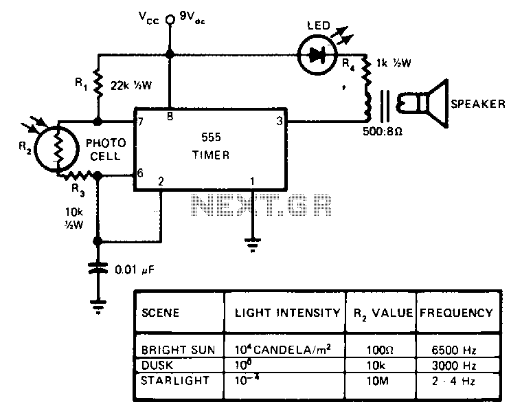
This circuit's frequency of oscillation increases directly with light intensity. The greater the light intensity, the higher the frequency of the oscillator. The 555 timer operates in the astable oscillator mode where frequency and duty cycle are controlled by...