
Audio Oscillator Ii
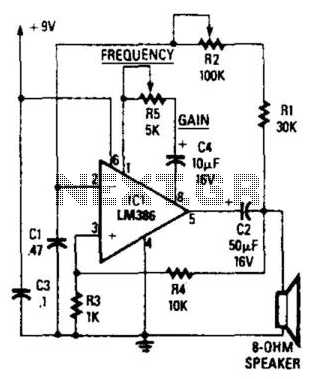
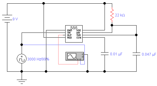
The described circuit operates as a frequency oscillator, where the output frequency is primarily determined by the capacitance values of capacitors C1 and C2, as well as the variable resistance provided by potentiometer R2. The formula f = 2.8 / [Cix(i1 + i2)] indicates that the frequency is inversely proportional to the total capacitance present in the circuit, which means that increasing the capacitance will decrease the frequency and vice versa.
In this configuration, IC1 functions as a voltage-controlled oscillator (VCO). The output from IC1 is a square wave, which is characterized by rapid transitions between high and low states. The non-inverting input at pin 3 receives feedback from the output of IC1, allowing for stable oscillation by maintaining the desired reference voltage. Capacitor C1 plays a crucial role in establishing the timing characteristics of the oscillation, as it charges up to the reference voltage and then discharges, creating the square wave.
Capacitor C2 is strategically placed to decouple the output, ensuring that any high-frequency noise generated during the oscillation does not affect the downstream components or the overall performance of the circuit. This decoupling helps maintain signal integrity and improves the reliability of the output signal.
The use of potentiometer R2 provides a convenient method for adjusting the frequency output, enabling flexibility in applications that require different frequency settings. By rotating the potentiometer, the resistance changes, which in turn alters the charging and discharging rates of capacitor C1, effectively varying the oscillation frequency within the specified range of 60 Hz to 20 kHz. This circuit can be utilized in various applications such as timers, tone generators, and signal modulation systems, where precise control over frequency is essential. The circuit"s frequency oscillation is /=2.8/ [Cix(/i + i2)]· Using the values shown, the output frequency can be varie d from 60 Hz to 20 kHz by rotating potentiometer R2. A portion of ICl"s output voltage is fed to its noninverting input at pin 3. The voltage serves as a reference for capacitor CI, which is connected to the noninverting input at pin 2 of the IC. That capacitor continually charges and discharges around the reference voltage, and the result is a square-wave output.
Capacitor C2 decouples the output. 🔗 External reference
Related Circuits
Detects clipping in preamp stages, mixers, amplifiers, etc. Single LED display powered by a 9V battery. This circuit is intended for use as a standalone unit. The clipping detection circuit is designed to monitor audio signals in various electronic devices...
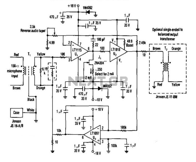
A low-noise LT1115 (Linear Technology, Inc.) operational amplifier is connected to a class-A buffer amplifier to create a variable gain (12-to-50 dB) microphone preamplifier. Total harmonic distortion (THD) is less than 0.01% across a frequency range from 80 Hz...
A year ago, a Class-D amplifier was designed based on the TAS5162, PCM1808, and TAS5086. Over the past year, several hundred samples were produced for sale to radio amateurs. Most devices function correctly without issues reported by consumers. However,...
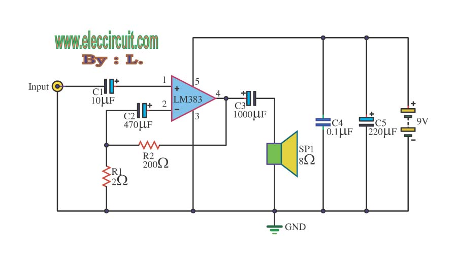
The circuit operates with a 9-volt power supply using the LM386 amplifier IC, which has a power output range of 300-800 mW, depending on the supply voltage, which can vary from 4 to 15 volts. The input signal is...
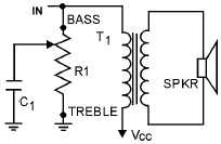
An audio tone control integrates both bass and treble controls within a single circuit. Such tone controls are typically found in lower-end audio equipment, as they conserve front panel space and require only one control knob instead of two...
The standard assumption is that the phase shift sections operate independently. According to the equation provided, the loop phase shift reaches -180 degrees when the phase shift of each section is 60 degrees. This condition is met when ω...