
audio peak indicator
A peak level indicator circuit typically comprises a few essential components: an input stage, a signal conditioning stage, a peak detection stage, and an output stage. The input stage usually consists of an operational amplifier (op-amp) configured as a non-inverting amplifier to ensure that the incoming audio signal is adequately amplified without distortion.
The signal conditioning stage may include filters to eliminate unwanted noise and ensure that only the desired frequency range is processed. This stage may also involve a rectifier circuit, which converts the AC signal into a DC voltage proportional to the peak level of the audio signal.
The peak detection stage is critical, as it captures the maximum voltage level of the incoming signal. This is often achieved using a peak detector circuit, typically implemented with a diode and a capacitor. The diode allows current to flow in one direction, charging the capacitor to the peak voltage level, while the capacitor holds this charge, providing a stable DC voltage that represents the peak level of the input signal.
Finally, the output stage may include a visual indicator, such as an LED or an analog meter, to provide a clear visual representation of the peak level. The LED can be configured to illuminate when the signal exceeds the predetermined threshold, thus serving as a warning to the operator.
In summary, a peak level indicator is an essential tool in audio signal processing, ensuring that signals remain within acceptable limits to avoid distortion or clipping. Its design focuses on responsiveness to brief signals, making it a vital component in various audio applications.A peak level indicator when a signal exceeds a certain maximum value. It can be quite useful, for instance, with tape recorders, mixing consoles etc. One of the most important requirements of a peak level indicator is that it should respond to very short signals.. 🔗 External reference
Related Circuits
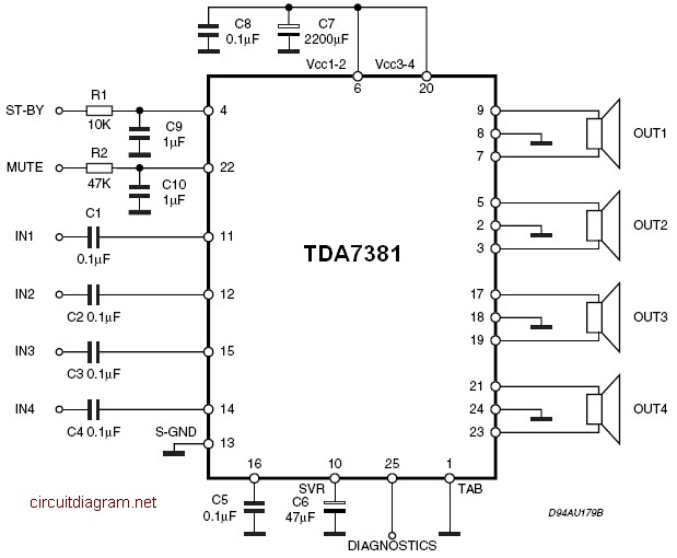
The amplifier is a quad amplifier circuit (amplifier with four inputs and four outputs) based on the TDA7381. This amplifier is designed for car audio systems, but it can also be utilized for other applications. The circuit has a...
With this circuit can determine whether any of the phones of the same line is busy (it's up the handset), with the help of a LED. The circuit has no measurable effect on the telephone, so that there are...
This is a circuit that generates white noise, rolled-off to drive earphones or a small speaker. White noise creates is a "rushing" sound, which sounds something like air rushing by your ear(s). White noise would be flat with frequency,...
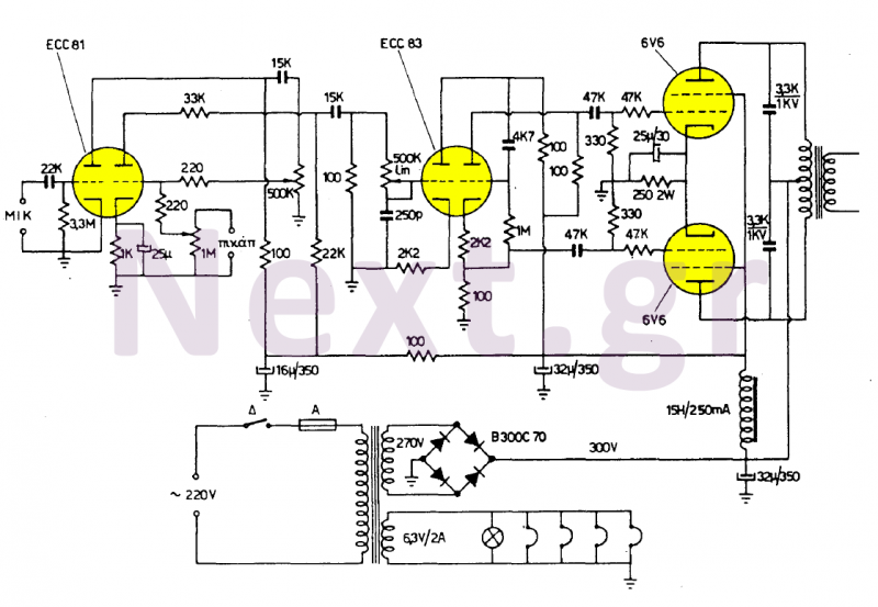
These two amplifiers are of high quality, simple, and economical to manufacture. They feature two inputs: one for a 4mV (500KΩ) sensitivity microphone and another for any 200mV (1MΩ) sound source, with the first input designated for speech and...
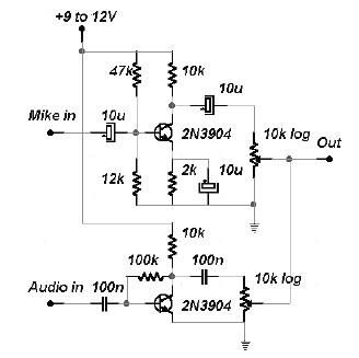
This two-channel audio mixer utilizes 2N3904 transistors to create two preamplifiers. The first preamplifier is designed for high gain, suitable for microphone input, while the second preamplifier allows for control over the audio level input. The audio mixer requires...
This is a diagram of a car audio active loudspeaker utilizing the LF353 operational amplifier from National Semiconductor. For optimal performance, the NE5532 is recommended to split the audio signal into three frequency bands using an active filter. The...
Warning: include(partials/cookie-banner.php): Failed to open stream: Permission denied in /var/www/html/nextgr/view-circuit.php on line 713
Warning: include(): Failed opening 'partials/cookie-banner.php' for inclusion (include_path='.:/usr/share/php') in /var/www/html/nextgr/view-circuit.php on line 713