
Audio peak indicator circuit
An audio peak indicator circuit is designed to visually represent the peak levels of an audio signal, providing critical information for audio engineers and musicians regarding signal strength and potential clipping. The circuit typically consists of a few essential components: a diode, a capacitor, a resistor, and an LED or a series of LEDs for visual indication.
The input audio signal is fed into the circuit, where it first encounters a diode. The diode's role is to rectify the audio signal, allowing only the positive half-cycles to pass through. This rectified signal is then smoothed out by a capacitor, which charges to the peak voltage of the incoming audio signal and discharges slowly, providing a stable voltage level that corresponds to the peak amplitude.
A resistor is often included in parallel with the capacitor to control the discharge rate, allowing the LED to remain lit for a short duration after the peak has passed. This creates a more noticeable indication of the peak level. The LED is connected in such a way that it lights up when the voltage across the capacitor reaches a certain threshold, indicating that the audio signal has hit a peak level.
The circuit can be calibrated to respond to specific voltage levels, making it adaptable for various audio applications. By adjusting the resistor and capacitor values, the response time and sensitivity of the peak indicator can be fine-tuned to suit different audio environments. This circuit is particularly useful in live sound reinforcement, studio recording, and broadcasting, where monitoring audio levels is crucial to maintaining sound quality and preventing distortion.Circuit audio peak indicator circuit schematics Circuit Electronics, Schematics for audio peak indicator circuit Circuit Electronics.. 🔗 External reference
Related Circuits
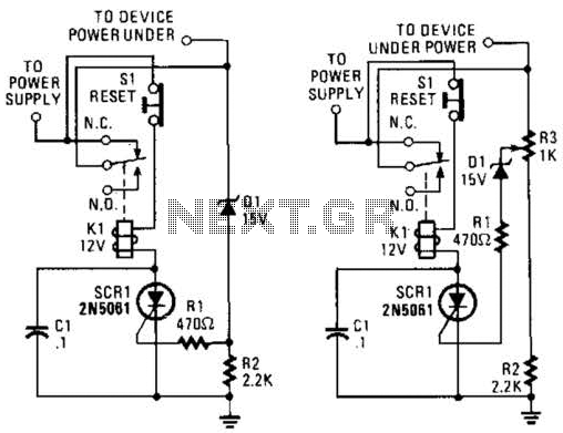
If circuits experience frequency overvoltage conditions, continually replacing blown fuses can become quite costly. This shutdown circuit addresses that issue by substituting the fuse with a relay and a low-current SCR. When the input voltage exceeds the threshold established...
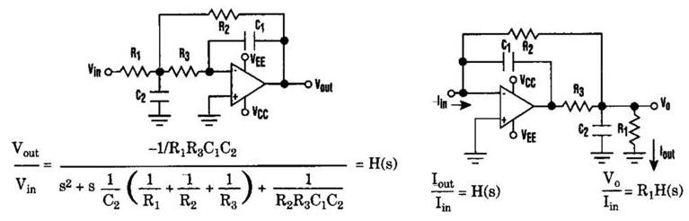
Current-Driven Sallen-Key Filter Circuit Diagram. The low-pass Sallen-Key filter is a staple for designers because it contains few components (A). The Sallen-Key filter is a widely used active filter topology that employs operational amplifiers (op-amps) to achieve desired filtering...
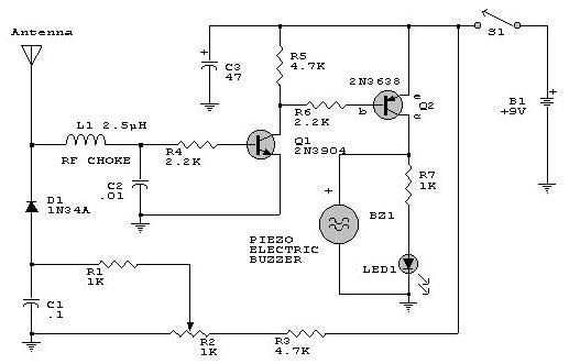
This electronic RF detector project is constructed using common transistors and a few standard electronic components. The RF detector is capable of responding to RF signals below the standard broadcast band and extending to over 500 MHz, providing both...
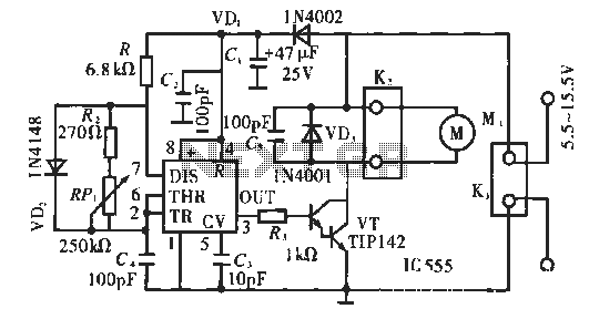
The circuit operates using pulse position modulation, which is a method distinct from the more commonly utilized pulse width modulation for speed control. A 555 timer is employed as a square wave modulator, generating output pulses with a fixed...
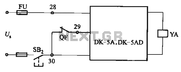
The DK-5A and DK-5AD AC power control circuit is illustrated in Figure 6-77. The figure includes a closing button (SBz) and a line (YA) connected to the closing electromagnet coil (U). This circuit is designed for the operation of...
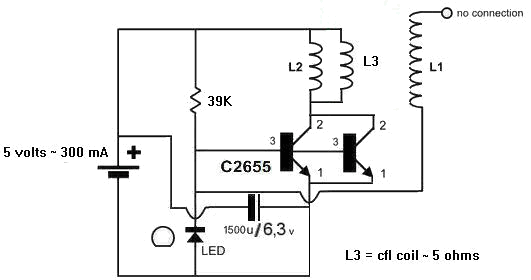
A 1N4148 diode and a 1-megohm resistor are included in the circuit. The inquiry pertains to how to power LED(s) using a 1.5-volt battery. There is also a question regarding the role of an additional coil, L3, and its...