
Audio-power-amplifier
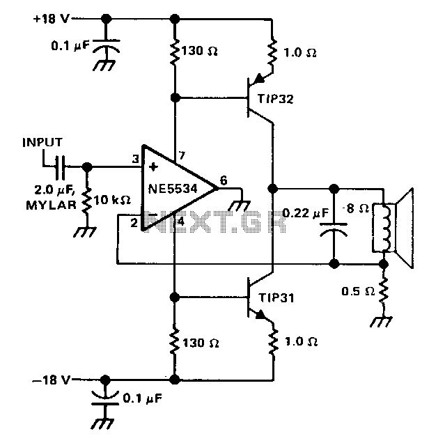
The single speaker amplifier circuit utilizes current feedback instead of the more commonly used voltage feedback. The feedback loop originates from the junction of the speaker terminal and a 0.5-ohm resistor, connecting to the inverting input of the NE5534 operational amplifier. When the amplifier input is positive, the power supply delivers current through the TIP32 transistor and the load to ground. Conversely, when the input is negative, the TIP31 transistor provides current through the load to ground. The gain is set to approximately 15, calculated as gain = SPKR 8 ohms / 0.5 ohms feedback. A 0.22 µF capacitor placed across the speaker limits its response to frequencies beyond the desired range.
Using the specified 0.22 µF capacitor, the amplifier's current output is reduced by 3 dB at 90 kHz, where the speaker impedance is approximately 20 ohms. To establish the recommended class A output collector current, the value of either 130-ohm resistor should be adjusted. An output current ranging from 50 to 100 mA will create an optimal operating midpoint, balancing minimal crossover distortion with manageable power dissipation.
The single speaker amplifier circuit is designed for efficient audio amplification by leveraging current feedback, which can provide better linearity and performance in certain applications compared to voltage feedback systems. The NE5534 operational amplifier is a high-performance device known for its low noise and high slew rate, making it suitable for audio applications.
The feedback loop configuration enhances stability and reduces distortion by ensuring that the output closely follows the input signal variations. The TIP32 and TIP31 transistors serve as the output stage, providing the necessary current drive to the speaker load. The choice of a 0.5-ohm resistor in the feedback path is critical as it helps define the gain of the amplifier while also playing a role in the overall stability of the circuit.
The inclusion of a 0.22 µF capacitor across the speaker is a strategic decision to filter out high-frequency signals that may not be desirable in the audio output, effectively rolling off the response at frequencies above 90 kHz. This characteristic is particularly important in audio applications where clarity and fidelity are paramount.
Adjusting the 130-ohm resistor allows for fine-tuning of the collector current, which is essential for achieving the desired operating point in class A operation. This adjustment is crucial for minimizing crossover distortion—a common issue in audio amplifiers—while also preventing excessive power dissipation that could lead to overheating and potential damage to the circuit components.
Overall, this single speaker amplifier circuit design demonstrates a thoughtful approach to audio amplification, emphasizing the importance of component selection and configuration to achieve high-quality sound reproduction.The single speaker amplifier circuit uses current feedback, rather than the more popular voltage feedback. The feedback loop is from the junction of the speaker terminal and a 0.5-0 resistor, to the inverting input of the NE5534.
When the input to the amplifier is positive, the power supply supplies current through the TIP32 and the load to ground. Conversely, with a negative input, the TIP31 supplies current through the load to ground. The gain is set to about 15 (gain = SPKR 8 0/0.5 0 feedback). The 0.22-!LF capacitor across the speaker rolls off its response beyond the frequencies of interest.
Using the 0.22-!LF capacitor specified, the amplifier current output is 3 dB down at 90 kHz where the speaker impedance is about 20 0. To set the recommended class A output collector current, adjust the value of either 130-0 resistor.
An output current of 50 to 100 mA will provide a good operating midpoint between the best crossover distortion and power dissipation. 🔗 External reference
Related Circuits

This audio amplifier design utilizes TMOS Power FETs configured in a complementary common-source arrangement. The FETs are biased to cutoff and can rapidly turn on when a signal is applied. This design approach offers significant thermal stability in the...