
Audio Power Meter: Shows Your Audio Amplifier
The circuit for measuring amplifier output power typically includes a few essential components: a resistive load, a voltage divider, and a microcontroller or analog meter for display purposes.
To construct the circuit, first, select an appropriate resistive load that matches the impedance of the amplifier output, usually 4 or 8 ohms for audio applications. This load will dissipate the power generated by the amplifier, allowing for accurate measurement.
Next, a voltage divider can be employed to scale down the voltage across the load resistor to a level suitable for measurement. The voltage divider consists of two resistors; the values should be chosen based on the maximum expected output voltage from the amplifier to ensure that the scaled voltage does not exceed the input range of the measuring device.
The output from the voltage divider can be fed into either an analog voltmeter or an analog-to-digital converter (ADC) connected to a microcontroller. If using a microcontroller, the measured voltage can be processed to calculate the output power using the formula:
Power (P) = (V^2) / R
where V is the voltage across the load, and R is the resistance of the load. The microcontroller can then display the calculated power on an LCD or LED display for easy reading.
For enhanced functionality, the circuit can be designed with additional features such as peak hold, averaging, or even wireless transmission of the measurement data. Proper calibration of the circuit is essential to ensure accurate readings, which may involve using known reference signals or adjusting the voltage divider based on the specific characteristics of the amplifier being tested.
Overall, this circuit serves as a valuable tool for audio engineers and hobbyists alike, providing real-time feedback on amplifier performance and enabling optimization of audio systems.Using this circuit, you can measure the actual output power of your amplifier.? You can put this circuit in a box as a measurement instrument, or you can. 🔗 External reference
Related Circuits
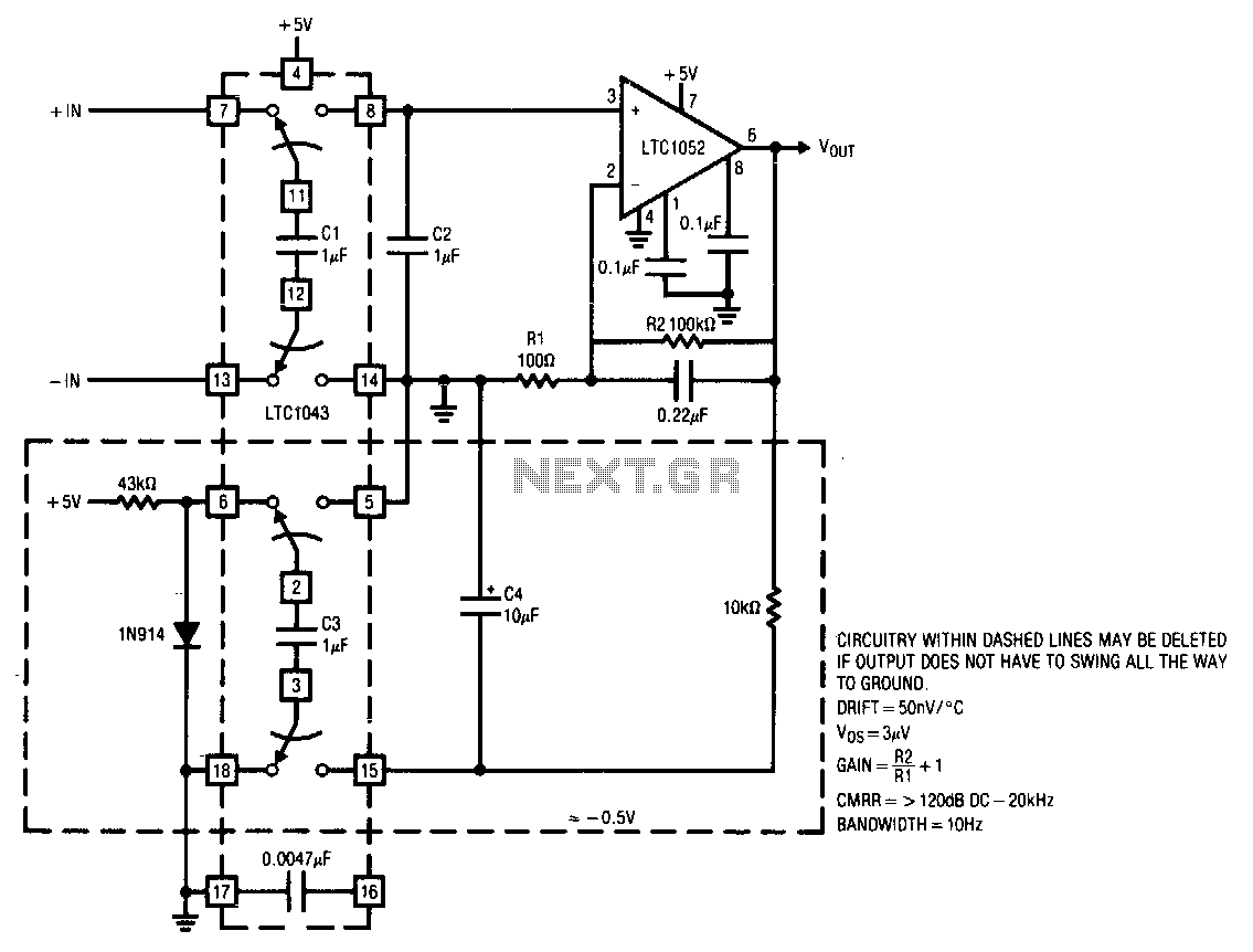
This circuit operates from a single 5 V power supply. The LTC1043 switched-capacitor instrumentation building block facilitates a differential-to-single-ended transition using a flying-capacitor technique. The circuit alternately samples the differential input signal and charges the ground-referred capacitor C2 with...
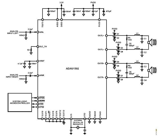
This is a stereo circuit schematic of the ADAU1592, a 2-channel, bridge-tied load (BTL) switching audio power amplifier. The ADAU1592 can be utilized in compact television sets, PC audio systems, and mini-component applications. According to the ADAU1592 datasheet, an...
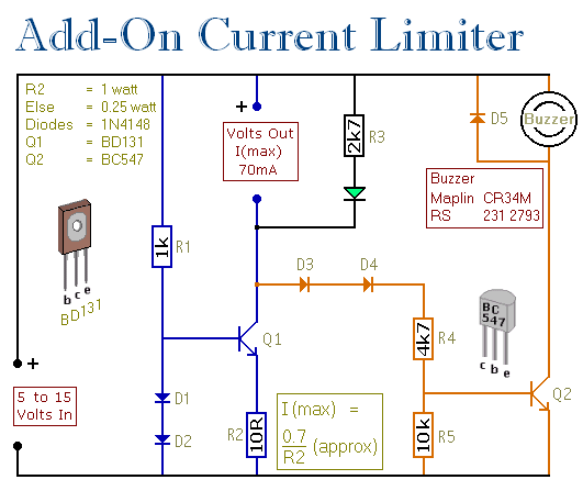
This circuit allows for setting a limit on the maximum output current from a power supply unit (PSU). It is particularly useful for initial project power-ups or during soak tests. By establishing an upper current limit, it protects both...
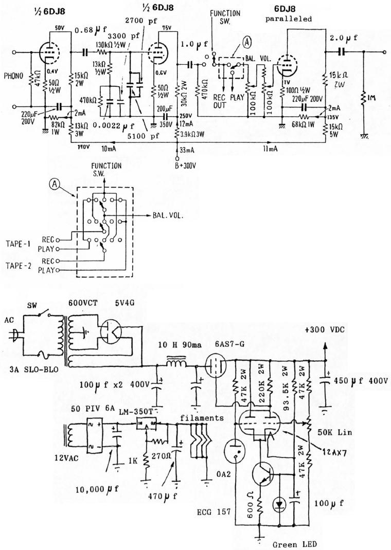
6DJ8 Tube RIAA Phono and Line Preamplifier Schematic. The high-tension (HT) power supply employs tube rectification and regulation. The 6DJ8 tube RIAA phono and line preamplifier schematic is designed to amplify audio signals from phono cartridges and line-level sources, utilizing...
This small circuit is a linear amplifier for driving small UHF TV transmitters. Its gain is 7 dB and can amplify a signal between 450-800 MHz. You can drive the circuit with 1 to 1.5 Watts signal. Better use...
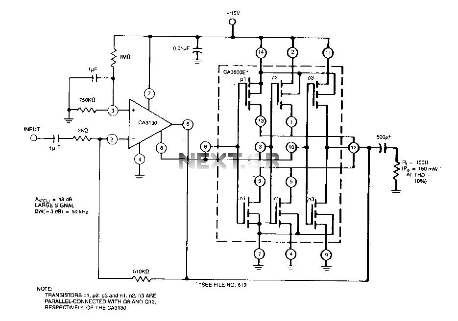
This circuit effectively enhances the current-sourcing and current-sinking capabilities of the CA3130 BiMOS operational amplifier. This configuration increases the current-handling capacity of the CA3130 output stage by approximately 2.5 times. The circuit described is designed to augment the output performance...