
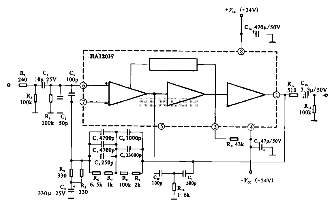
Audio Preamplifier circuit diagram with low distortion
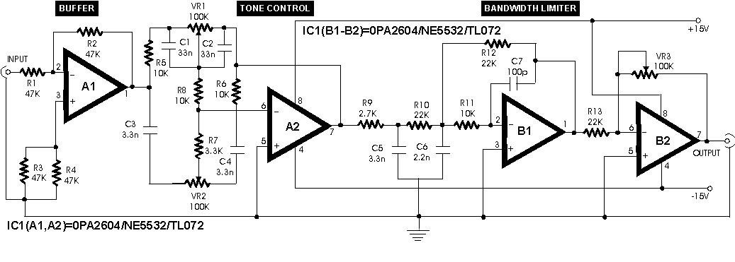
The audio preamplifier circuit is designed to provide high fidelity sound reproduction and low distortion, making it suitable for both professional and home audio applications. The choice of the OPA2604 op-amp is particularly advantageous due to its low noise characteristics and high performance, which are critical in maintaining audio quality. The FET input stage offers a high input impedance and low bias current, minimizing signal degradation and noise introduction. The Baxandall filter circuit allows for effective tone control, enabling the user to adjust the audio output to their preference while maintaining signal integrity. The low-pass filter function of the bandwidth limiter ensures that only the desired frequency range is amplified, effectively reducing unwanted high-frequency noise.
The power supply design is flexible, accommodating a range of voltage inputs, which enhances the circuit's versatility in various applications. The low current consumption of 10 mA contributes to energy efficiency, making the preamplifier suitable for battery-operated devices as well. The careful consideration of component selection and circuit layout contributes to the overall performance, ensuring that the amplifier meets the demands of high-quality audio reproduction. Proper setup and configuration are essential to achieving optimal performance, emphasizing the importance of checking voltage symmetry and the integrity of connections throughout the circuit.In an audio amplifier the quality of sound depends upon a number of factors, e. g. quality of active and passive components, circuit configuration, and layout. To an extent, the selection of components depends on the constructor`s budget. The discrete active components like transistors have been increasingly replaced by linear ICs, making the task of designer easier. With the passage of time, the general-purpose op-amps like LM741, which were being used in audio/hi-fi circuits, have become The preamplifier circuit presented here is based on a dual precision op-amp for the construction of a low distortion, high quality audio preamplifier. A dual op-amp OPA2604 from Burr-Brown is used for all the stages. The FET input stage op-amp was chosen in this context it is worthwile to mention another popular bi-polar architecture op-amp, the NE5534A.
It has, no doubt, an exceptionally low noise figure of 4nV/G–Hz but rest of the specifications compared to OPA2604 are virtually absent in this IC. Also This IC is also capable of operating at higher voltage rails of ± 24V (max. ). Also its input bias current (100 pA) is many orders lower than its bipolar counterpart`s. This ensures a multifold reduction in noise. A channel seperation of 142 dB exists between In the circuit, buffer is essential for the proper working of the subsequent blocks.
A nominal input impedance of 47k is offered by this stage which prevents overloading of the preamplifier. The tone control is a baxandall type filter circuit. The bandwidth limiter is basically a low-pass filter with an upper cut-off ceiling at the end of the useful audio spectrum.
The gain at 10 kHz is approximately 17 dB. The design is essentially 3-pole type and the upper frequency is set at 25 kHz. This lSetting the unit is fairly simple. Check the power leads feeding the IC for symmetrical voltages. High quality audio output from the line output socket is to be fed as the input signal to this preamplifier. Output of the preamplifier is fed to the power a The whole circuit consumes about 10 mA when the above-mentioned ICs are used.
Power supply requirements are not critical as the circuit works on 7. 5V to 15V DC. Disclaimer: All the information present on this site are for personal use only. No commercial use is permitted without the prior permission from authors of this website. All content on this site is provided as is and without any guarantee on any kind, implied or otherwise. We cannot be held responsible for any errors, omissions, or damages arising out of use of information available on this web site.
The content in this site may contain COPYRIGHTED information and should not be reproduced in any way without prior permission from the authors. 🔗 External reference
Related Circuits
This circuit is connected to a motorcycle and is integrated into a circuit that is powered only when the key is in the "ON" position. If the motorcycle is turned off using the kill switch while the key remains...
This is a low-cost 150-watt amplifier circuit with a diagram and schematic design utilizing two Darlington power transistors, TIP142 and TIP147. The 150-watt amplifier circuit is designed to provide high power output while maintaining cost efficiency, making it suitable for...
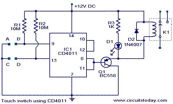
The following circuit illustrates a Touch Switch Circuit Diagram. This circuit is based on the CD4011 IC. Features include R1 and R2, which are the logic gates of the circuit. The Touch Switch Circuit utilizes the CD4011 integrated circuit, which...
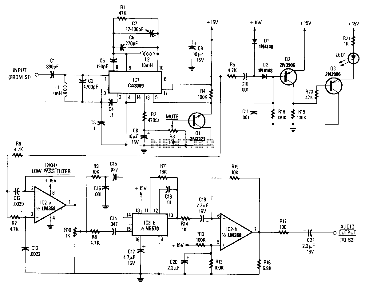
The baseband audio input originates from the pole of switch S1 in the stereo decoder and is coupled to IC1 (a CA3089) via a 78.6 kHz bandpass filter composed of capacitors C1 and C2, along with inductor L1. IC1...

A hydrophone is a device similar to a microphone, designed specifically for use in underwater environments. When utilized to capture sound in air, its effectiveness diminishes. A hydrophone operates by converting sound waves into electrical signals, making it an essential...
Low-noise preamplifier circuit. This circuit demonstrates a typical low-noise preamplifier design, which can be utilized to amplify signals from sources such as magnetic heads and microphones within audio applications. The input signal is coupled through a capacitor and subsequently...