
audio processor circuit using ic ssm2045
The audio processor circuit utilizes the SSM2045 IC, known for its effectiveness in electronic music applications, particularly in signal processing tasks that require precise control over audio signals. The integration of the 741 op-amp enhances the circuit's ability to convert current output into a usable voltage signal, making it suitable for further audio processing stages.
The low-pass filter configuration is essential for eliminating high-frequency noise and ensuring a smooth audio output. The selection of a 2-pole output at pin 1 and a 4-pole output at pin 8 allows for versatility in output options, catering to different audio processing needs. The use of VCAs facilitates dynamic control over the audio signal, enabling adjustments to gain and balance in real-time, which is critical in live performance settings.
Resistors R15 and R16 play a crucial role in maintaining signal integrity by minimizing offset errors and suppressing unwanted control voltage variations. The volume control provided by potentiometer P4 allows for user-friendly adjustments to the output level, enhancing the overall usability of the circuit.
The specified input level of 150 mVpp and the ability to handle source impedances up to 200 ohms indicate that the circuit is designed to interface with typical audio sources, ensuring compatibility with a wide range of equipment. The VCA's response to a 0 dBm input level, resulting in a 6 dB attenuation, reflects the circuit's design considerations for managing audio dynamics.
The adjustable cutoff frequency, ranging from 20 Hz to 20 kHz, is a significant feature that allows users to tailor the filter's response to suit specific audio requirements. The Butterworth characteristics of the filter are achieved through careful selection of capacitor values, ensuring a flat frequency response within the passband.
The necessity for DC decoupling from the second IC emphasizes the importance of preventing DC offsets from affecting subsequent stages in the audio processing chain. The noise-to-voltage ratio of approximately 80 dB indicates a high level of signal clarity, making this audio processor circuit a valuable component in high-fidelity audio systems.This audio processor circuit features the SSM2045 IC which was developed specially for electronic music applications and the 741 opamp IC. The circuit is configured as a low pass filter with a DC voltage control for gain. The input signal is set to a working level of 150mVpp through the resistor R1. The filter has 2 buffered outputs: the 2-pole ou tput at pin 1 and 4-pole output at pin 8. Internally, the outputs are connected to 2 voltage-controlled-amplifiers (VCA). The R15 and R16 are connected to these outputs to achieve optimum offset and control voltage suppression. P4 is the volume control. The current that flows to the pins 15 and 16 should not go beyond the maximum of 250 µA. The balance of the two VCAs and the entire filter is being controlled be a voltage range of -250 mV to + 250 mV at pin 14.
This voltage can be set by P2. The input can be driven with source impedances up to a maximum of 200. With an input level of 0dBm, the VCA weakens by 6 dB. The bias current needed at pin 17 is between 120 µA and 185 µA. The cutoff frequency can be shifted between 20 Hz and 20 kHz with a variable voltage at pin 5. This can be varied through P1. The capacitor values were selected to give the filter its Butterworth characteristics. The output current of the SSM2045 IC is converted to a voltage output by the 741 opamp. Any sybsequent circuit must be DC decoupled from IC2. The noise-voltage ration is about 80 dB. 🔗 External reference
Related Circuits
The circuit diagram represents a simple parking sensor system that measures the distance between the rear bumper of a vehicle and obstacles located behind it. The schematic consists of two main components: the transmitter and the receiver. The distance...
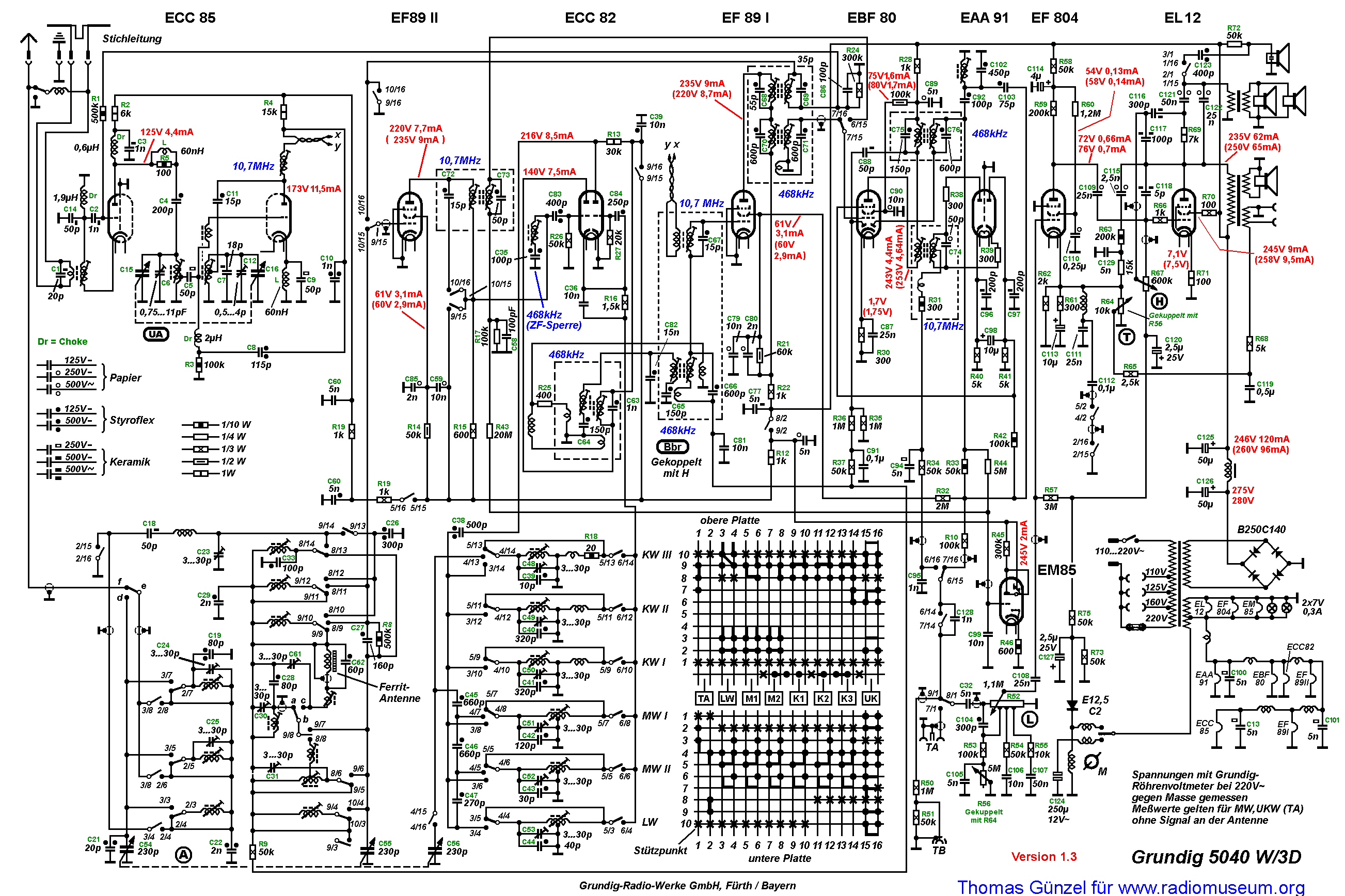
The primary winding of the first IF transformer lacks a capacitor, indicating that it functions as a single tuned circuit with the primary coil serving solely as an inductive coupling. The routing of the twisted pair cannot be replicated...
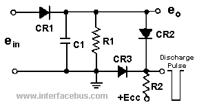
A peak detector is a circuit that detects the peak voltage of an incoming waveform. It is primarily used as an Amplitude Modulation (AM) detector, Pulse Amplitude Modulation (PAM) detector, or envelope detector. The basic form of a peak...

This circuit is a compact timer designed to keep the headlights of a car illuminated for approximately 1.5 minutes before automatically turning them off. By integrating this circuit into a vehicle, users can access dark areas without the need...
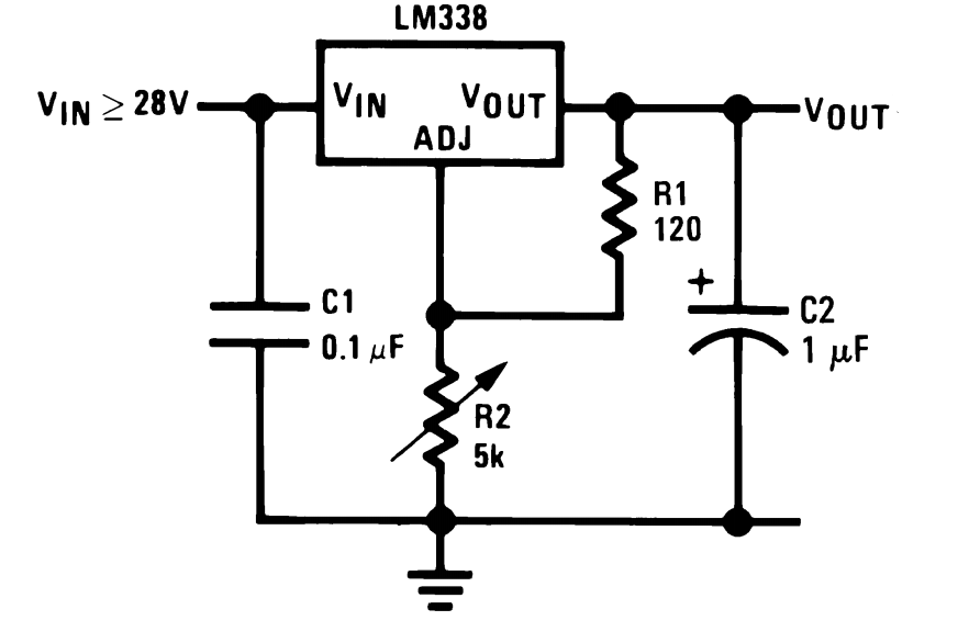
The LM338 integrated circuit (IC) from Texas Instruments is a versatile component that can be configured in various ways to create high-quality power supply circuits. The first circuit demonstrates the typical wiring format around the IC, providing an adjustable...
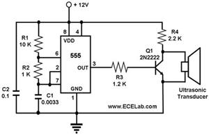
The ultrasonic cleaning machine functions as a humidifier and operates on a simple circuit primarily consisting of an ultrasonic oscillator. It generates ultrasonic frequency signals, typically within the range of 20-40 kHz, using a transistor. These signals are transmitted...