
Audio Resonant Equalizer Circuit Design
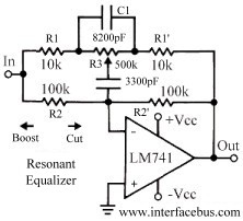
The resonant equalizer circuit is designed to enhance the audio signal by selectively boosting or attenuating frequencies around a designated center frequency. This is achieved through the careful arrangement of capacitors and resistors, which define the circuit's frequency response characteristics. The operational amplifier, typically the LM741, is configured in a feedback loop that allows for precise control over the gain applied to the audio signal.
In this circuit, the high-pass and low-pass filters are integrated to form a bandpass characteristic, where the gain can be adjusted symmetrically around the center frequency. The use of capacitors in the feedback path enables the circuit to alter the frequency response dynamically, providing versatility in audio processing applications. The symmetrical nature of the response curve indicates that any adjustments made to boost high frequencies will correspondingly affect low frequencies, maintaining a balanced output.
To implement this resonant equalizer, one must calculate the appropriate values for the capacitors and resistors based on the desired center frequency and bandwidth. The equations governing the frequency response will take into account the selected octave ratios, allowing for fine-tuning of the equalizer's performance. This adaptability makes the resonant equalizer suitable for various audio applications, from live sound reinforcement to studio mixing environments.
The ability to cascade multiple resonant equalizers allows for the creation of complex audio processing chains, where different frequency bands can be independently controlled. This feature is particularly beneficial in professional audio settings, where precise tonal adjustments are necessary for achieving a polished sound. The integration of this circuit into an audio mixer further enhances its utility, enabling sound engineers to manipulate the audio signal with precision and clarity.This topic covers a resonant equalizer which is a different style circuit than the common audio equalizer, although both produce the same result. The difference here is that the frequency response of both the high and low frequency equalizer covered on the previous page overlap each other.
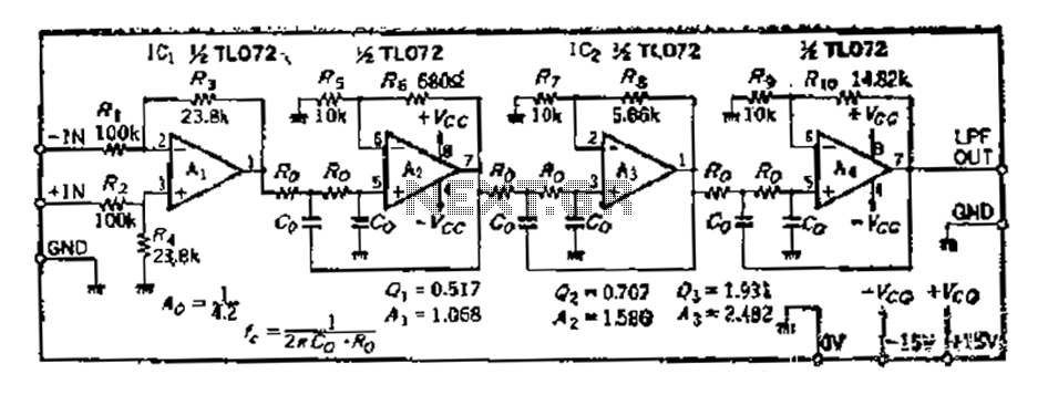
Notice how the capacitor placement for the high-pass equa lizer and the capacitor placement for the low-pass equalizer are used in this circuit design. This circuit is also sometimes called a universal equalizer, because by changing or adding the capacitors any of the three equalizer responses can be produced. Although this schematic only shows one possible example, the other two were shown in the previous design.
The circuit design is almost identical to the unity gain 741 circuit used before. The only difference is the addition of the second capacitor to the circuit schematic. As with all these circuits, the general purpose LM741 is only used to represent almost any operational amplifier. Also see Manufacturers of Op Amps. This circuit basically combines the low and high pass filters, similar to circuits found on the Passive Tone Control page, or the Active Tone Control page.
The low and high frequency points are combined and placed symmetrically above and below center resonant frequency. The resonant equalizer functions around a particular center frequency and than adds gain or attenuation above or below that frequency.
However the response only effects a certain range above or below the center frequency, as shown in the graphic. Which appears just like a bandpass filter, with the additional characteristic of both gain and attenuation control.
As shown in the graphic to the right the boost an cut are symmetrical. The high frequency [Fh] 3dB point and the low frequency [Fl] 3dB points are also symmetrical around the center frequency. So the first calculation to be perform is to determine the number of octaves the equalizer functions over: So the equalizer circuit above adjusts the frequency response of an audio signal slightly above or below a particular center frequency.
Additional circuits could be designed that are centered on other frequencies resulting in a number of frequency controls each operating over a different frequency band. Each of the different outputs from the individual equalizers could be applied to an Audio Mixer so their combined effect could be felt over a single audio channel.
Using the ratio [octave] selection in the equation each equalizer could be made as wide or narrow as desired. 🔗 External reference
Related Circuits
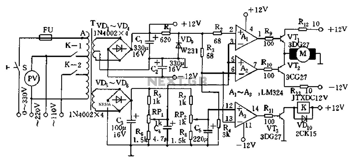
Automatic AC voltage regulator circuit TXD1742 with continuous adjustment. The TXD1742 is an automatic AC voltage regulator circuit designed to provide continuous voltage adjustment, ensuring stable output voltage in varying load conditions. This circuit is particularly useful in applications where...
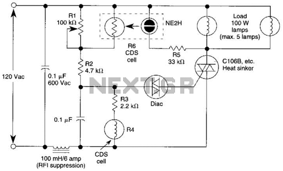
A neon bulb and a CdS photocell are enclosed in a light-tight enclosure to form an optocoupler. A diac/triac combination is employed to create a snap-switch effect. A second CdS photocell serves as the primary sensor. As darkness approaches,...
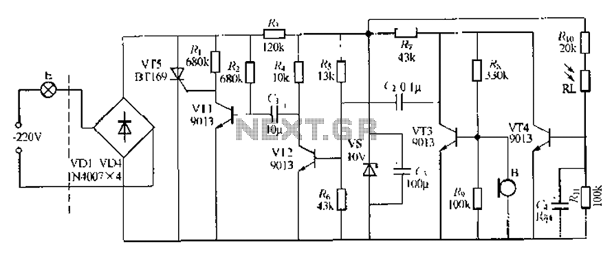
This circuit describes a sound and light control delay system for a walkway stairs light switch. It involves various components including 220V AC electric bulbs, diodes (VD1-VD4), and resistors. The circuit utilizes a rectifier regulator to stabilize the voltage...
The circuit illustrated relates to a standard industrial UPS (Uninterruptible Power Supply), demonstrating how the batteries assume control during an electrical outage. The Uninterruptible Power Supply (UPS) circuit typically consists of several key components that ensure a reliable power supply...
Based on the classic Baxendall tone control circuit, this provides a maximum cut and boost of around 10dB at 10K and 50Hz. The first BC109C transistor (left hand side) is acting as a buffer. It provides the circuit with...
A 36 dB/octave Butterworth filter consists of three sub-structures, each stage containing two filter sections. The design aims to achieve specific 3 dB frequency characteristics. The filter needs to be normalized to a value of 0 across all levels,...