
Audio Signal Generator
The circuit utilizes CMOS technology for its low power consumption and efficiency, making it ideal for battery-operated applications. The oscillator's core is based on a simple feedback loop involving the inverters, which generate a stable sine wave output. The choice of capacitors and resistors in conjunction with the variable resistor provides flexibility in tuning the frequency, allowing users to achieve the desired audio tone for various applications. The output stage employs an audio transformer, which not only facilitates the balanced output but also isolates the circuit from the load, ensuring that variations in load impedance do not affect the oscillator's performance. The dual output design caters to different interfacing needs, making this circuit versatile for both casual and professional use. Users can easily modify the circuit to suit specific requirements, such as adding additional frequency ranges or altering the output characteristics. Overall, this CMOS-based audio oscillator represents a practical and efficient solution for generating audio signals in a compact and user-friendly package.A couple of cheap CMOS ICs are used to digitally generate audio sinewaves across a wide range in this compact battery-powered test instrument. The oscillator features both unbalanced and balanced outputs. I use signal generators of one sort or another all the time as I design and build circuits. They include a pair of simple oscillators; a transis tor oscillator for testing crystals, and a CMOS square wave clock source, built on a scrap of PCB. I also have a homebrewed RF signal generator which covers up to about 50 MHz in a dozen ranges, and an audio signal generator. For many years, I used a kit-built audio oscillator, a design from the now defunct Electronics Australia (EA) magazine.
It used a couple of op-amps, and was stabilized with a thermistor. It worked, but it had some serious limitations. The output level would vary with frequency, and it was annoyingly microphonic. Knock it by accident, and it would make a "boinnngggg" sound over top of the wanted tone. The oscillator`s frequency also had a habit of drifting a little over time. The most critical limitation however was its power consumption. It seemed to gobble batteries! Whenever I went to use it again, the bothersome thing would require a (yet another!) new battery before I could begin to use it. Along with the one or two seconds it took to start up, a product of its thermistor stabilization scheme, I became sufficiently annoyed with it one day that I designed and built this simple CMOS-based version.
The oscillator described here is now more than a dozen years old. After all that time, and some fairly heavy use, I finally replaced the original 9V battery I put in when I built it about six months ago. It draws a miserly 3mA at 9V, but it is possible to power it with any voltage from 3V to as much as 15V, the limit of the CMOS chips.
If nothing else, it`s proved to be more battery efficient than the EA design, and as a result, it`s always ready for use. Operating from a single 9V battery, this audio oscillator covers from 300 Hz to 12 kHz in a single range.
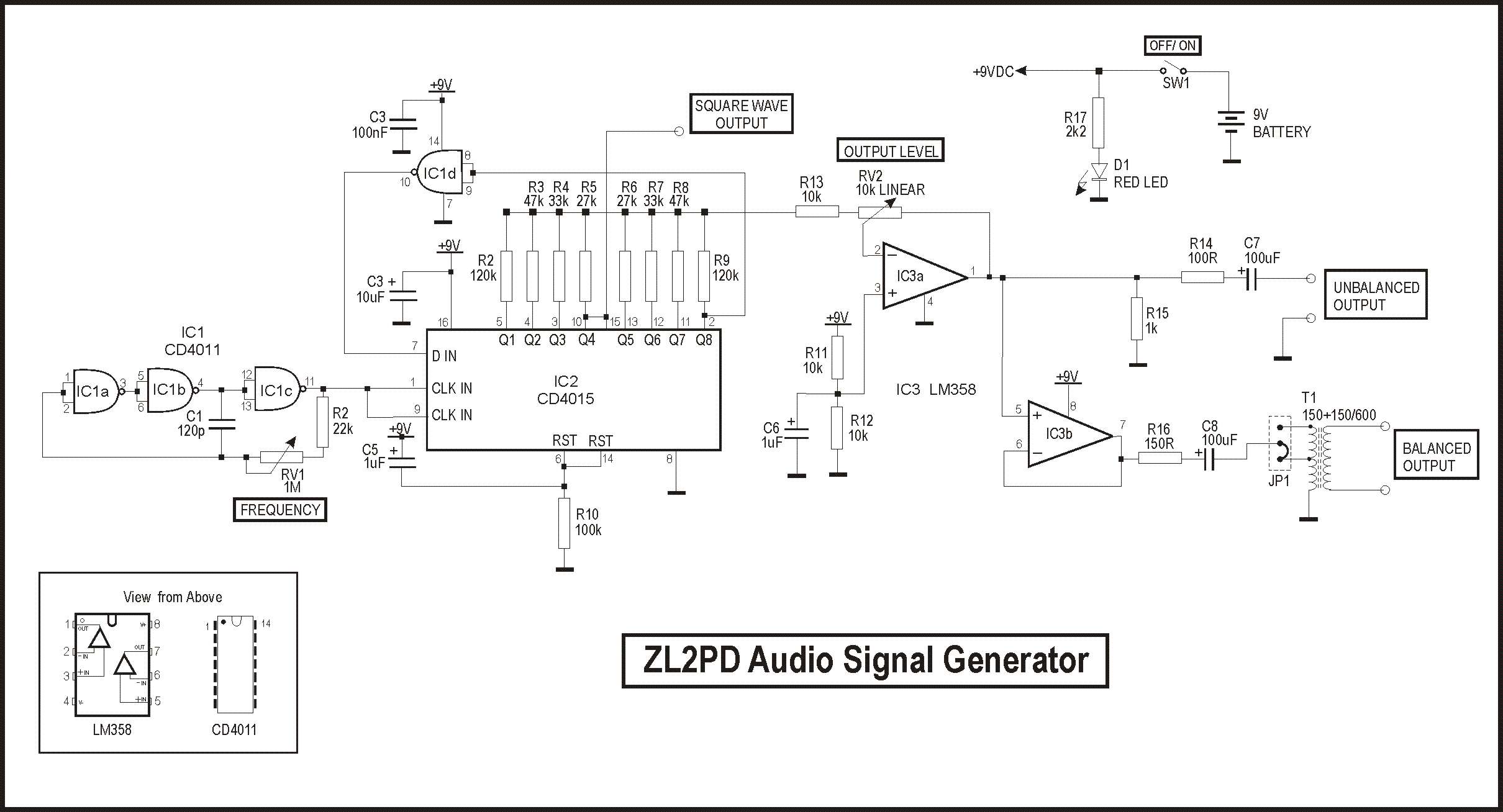
If you want a higher or lower range, it`s very easy to modify to add either an extra range or two, or change the range. This unit only provides a sinusoidal output. I`ve not needed a square wave generator to the same extent, and the little CMOS oscillator I built onto a scrap of PCB to generate a square wave some time back seems to be sufficient for my requirements (although it`s as ugly as anything!) However, a square wave output is available on the PCB, at pins 10 and 15 of IC2, for anyone that wants square waves too.
There are two outputs on this audio signal generator. The first is a standard unbalanced DC-isolated output with an impedance of about 100 ohms and an adjustable level up to at least 5 Vpp. This output is available on an "RCA" or "phono" female connector as well as a parallel-connected BNC connector.
Both are mounted on the front panel. These are the two most commonly used connectors around my bench, but you can obviously use any connectors you want if you want to build your own version of this unit. The second output is a balanced 600 ohm output. This is connected to a pair of banana plug terminal posts, again mounted on the front panel. The output level is similarly adjustable, and the open circuit isolated output reaches at least 9Vpp due to a compact 150 ohm to 600 ohm audio transformer inside the unit.
I measured an output level of +10dBm into a 600 ohm load with a fresh battery. This output is used for feeding 600 ohm professional audio interfaces such as VHF and UHF transmitters which I encounter from time to time in my work. The circuit is simplicity itself. (Right click your mouse on the digram over to the right to see the full detail) A CMOS square wave oscillator using three CMOS gates each wired as an inverter.
VR1 allows the frequency to be adjusted over a 40:1 range. Selecting one of two timing capacitors allows two rang 🔗 External reference
Related Circuits
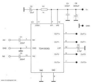
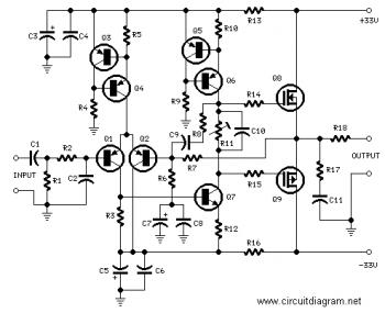
This is a 22-watt car stereo audio amplifier. The circuit is based on a single IC TDA1553 with a few peripheral components. This IC is designed for car audio applications. The TDA1553CQ integrates two 22-watt amplifiers with differential input...
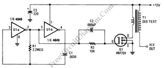
The schematic diagram below illustrates a high voltage generator circuit. This circuit employs a 4049 hex inverter functioning as an oscillator, with the option to utilize an ignition transformer from an automotive engine. A flyback transformer may also be...
There are two main types of oscillators: the most common is the Wein Bridge oscillator variety, which has low distortion but offers only sine wave output and can suffer from amplitude bounce as frequency changes. The second type, which...
This circuit can be directly connected to CD players, tuners, and tape recorders. It requires the addition of a 10K logarithmic potentiometer (dual gang for stereo) and a switch to accommodate various sources. Proper grounding is crucial to eliminate...
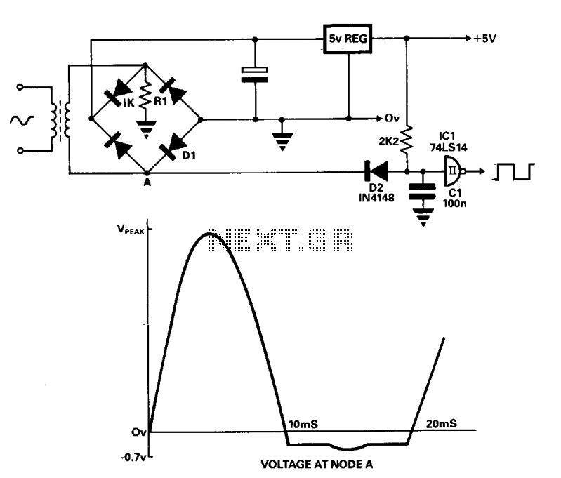
A line frequency square wave with a 1:1 duty cycle can be generated using only three components and a buffer from the power supply. During the alternate half-cycle, point A is clamped to approximately -0.7 V by diode D1...
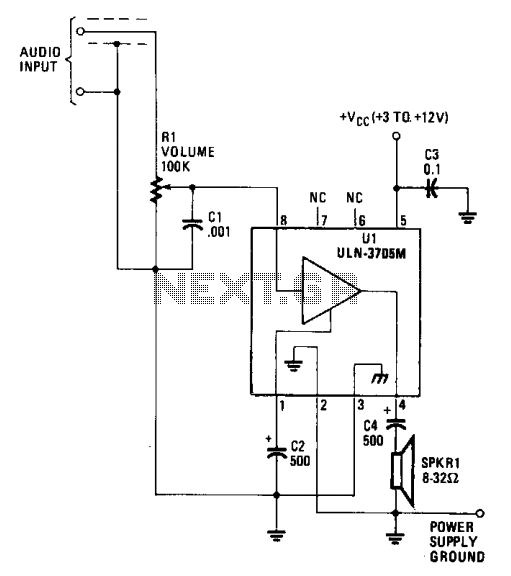
The amplifier functions with supply voltages up to 12 volts and can operate at lower voltages as low as 1.8 volts while maintaining acceptable distortion levels, albeit with reduced volume. Its power requirements make it suitable for applications powered...