
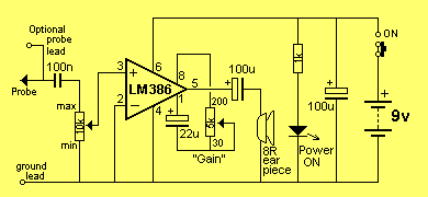
Audio Signal Testing amplifier
More: As we said, there can be lots of problems with audio stages. Sometimes they develop over a period of time, or they can be present from the moment the amplifier is assembled. You can also get intermittent faults, drop outs, squealing, motor-boating, distortion or simply lack of gain. The amplifier presented in this article is used as an audio probe by listening to the loudness and quality of the audio going into the stage under test and comparing it to the audio emerging from the output of the stage. You do this by putting the earpiece near your ear and listening carefully - that's why the probe has two long leads. We could write a book on fixing audio stages but to reduce it to one page, here is the approach: The simplest situation is a single transistor amplifier with a distorted output. The first thing to do is replace the transistor. Even though transistors are very reliable devices, you may have overheated it and this will cause the device to have a different gain and thus the voltages on the stage will not allow the signal to be processed correctly (you can put it back later if it is not the cause of the problem). The next thing is measure the voltage on the collector. Ideally it should be half-rail. This allows the transistor to turn on and off THE MAXIMUM AMOUNT and thus give the stage the maximum gain. To carry out any more investigation on the stage you will need a copy of the circuit diagram. This will let you know how the transistor is biased and may give details of the voltages at the various locations. Next look at the electrolytics. These can be inter-stage devices, decoupling or emitter bypass capacitors. They can dry-out and lose their capacitance or go open (very rarely) or go short-circuit (very rare). Tantalums can also go short-circuit as they are susceptible to high voltage spikes that puncture their ceramic substrate. If the transistor has an emitter by-pass capacitor in the form of an electrolytic across the emitter resistor, the stage gain will be severely reduced if the capacitor (electrolytic) has lost its capacitance (dried out). A faulty inter-stage capacitor (one that connects the output of one stage to the input of the next) can be checked by placing the probe one side of the capacitor, then the other. If the audio level drops considerably, the capacitor is not passing the signal and may be faulty. If you have replaced the transistor with another type, the voltage on the collector may be different to that specified. If it is lower, the transistor has a higher gain and the base-bias resistor must be increased. If it is higher than expected, the base-bias resistor must be decreased. This only applies to simple self-biasing stages, where the base-bias resistor sets the collector voltage for the stage. Resistors rarely give trouble except if they are of an old style or in a position where they get hot. If hum is present on the audio, the fault will lie in the filtering of the power supply. If a squeal similar to a feed-back squeal, (as heard when a microphone is too near the speaker of an amplifier), the fault can be in the decoupling capacitor. This is generally a small value electrolytic (10u to 100u) near the stage it is protecting and will be associated with a low value resistor on the power rail. The electrolytic is connected across the power rails. This electrolytic can also produce a fault similar to the putt-putt-putt of a motor boat exhaust system, bubbling through water. The Mini Bench Amp has a volume control in the form of a gain control, to vary the output volume from the earpiece. The approximate gain is marked around the control. An additional probe can be connected to the board via a small socket and this will allow the Mini Amplifier to be brought up to your ear so you can listen to the audio.
The mini audio amplifier described utilizes the LM386 operational amplifier, which is specifically designed for low voltage applications with a maximum output power of 1 watt. The amplifier is configured to operate in a single-ended mode, where the inverting input is connected to ground (negative rail) and the non-inverting input is connected through a coupling capacitor. This configuration allows for an AC audio signal to be amplified while blocking any DC offset.
The gain of the LM386 can be set by external resistors, and it typically operates with a gain of 20 to 200, depending on the configuration. The gain control feature allows the user to adjust the output volume to suit various applications, whether testing audio signals or driving a small speaker.
To effectively use this amplifier as an audio probe, it is essential to connect the earpiece to the output. The design includes two long leads for easy maneuverability, enabling the user to position the earpiece close to their ear while keeping the amplifier connected to the circuit under test. This setup allows for real-time monitoring of audio quality, facilitating troubleshooting of audio stages in various devices.
Common issues encountered in audio stages include distortion, intermittent faults, and gain loss, which can arise from faulty components such as transistors, capacitors, and resistors. The troubleshooting process involves checking the voltage levels at critical points in the circuit, such as the collector of the transistor, to ensure proper biasing and operation. Additionally, electrolytic capacitors are often scrutinized for signs of failure, as their degradation can significantly impact circuit performance.
In summary, this mini audio amplifier serves as a versatile tool for testing and diagnosing audio stages in various electronic devices. Its simple design, combined with the LM386's capabilities, makes it an invaluable asset for both hobbyists and professionals in the field of electronics.This mini audio amplifier will test the audio stages in amplifiers such as the front end of FM bugs. You can also use it on lots of our other projects as well as the output stages of radios. It is a very handy piece of test equipment and will make a perfect addition to your collection. The LM 386 is a high power op-amp. It is used to drive a speaker. The inverting input has been connected to the negative rail and the non-inverting input has been connected to a capacitor. Resistors inside the chip bias this input so that it only requires about 7mV before the chip turns on.
This voltage is called the off-set voltage. As we said, there can be lots of problems with audio stages. Sometimes they develop over a period of time, or they can be present from the moment the amplifier is assembled. You can also get intermittent faults, drop outs, squealing, motor-boating, distortion or simply lack of gain.
The amplifier presented in this article is used as an audio probe by listening to the loudness and quality of the audio going into the stage under test and comparing it to the audio emerging from the output of the stage. You do this by putting the earpiece near your ear and listening carefully - that's why the probe has two long leads.
We could write a book on fixing audio stages but to reduce it to one page, here is the approach: The simplest situation is a single transistor amplifier with a distorted output. The first thing to do is replace the transistor. Even though transistors are very reliable devices, you may have overheated it and this will cause the device to have a different gain and thus the voltages on the stage will not allow the signal to be processed correctly (you can put it back later if it is not the cause of the problem).
The next thing is measure the voltage on the collector. Ideally it should be half-rail. This allows the transistor to turn on and off THE MAXIMUM AMOUNT and thus give the stage the maximum gain. To carry out any more investigation on the stage you will need a copy of the circuit diagram. This will let you know how the transistor is biased and may give details of the voltages at the various locations.
Next look at the electrolytics. These can be inter-stage devices, decoupling or emitter bypass capacitors. They can dry-out and lose their capacitance or go open (very rarely) or go short-circuit (very rare). Tantalums can also go short-circuit as they are susceptible to high voltage spikes that puncture their ceramic substrate.
If the transistor has an emitter by-pass capacitor in the form of an electrolytic across the emitter resistor, the stage gain will be severely reduced if the capacitor (electrolytic) has lost its capacitance (dried out). A faulty inter-stage capacitor (one that connects the output of one stage to the input of the next) can be checked by placing the probe one side of the capacitor, then the other.
If the audio level drops considerably, the capacitor is not passing the signal and may be faulty. If you have replaced the transistor with another type, the voltage on the collector may be different to that specified. If it is lower, the transistor has a higher gain and the base-bias resistor must be increased. If it is higher than expected, the base-bias resistor must be decreased. This only applies to simple self-biasing stages, where the base-bias resistor sets the collector voltage for the stage.
Resistors rarely give trouble except if they are of an old style or in a position where they get hot. If hum is present on the audio, the fault will lie in the filtering of the power supply. If a squeal similar to a feed-back squeal, (as heard when a microphone is too near the speaker of an amplifier), the fault can be in the decoupling capacitor.
This is generally a small value electrolytic (10u to 100u) near the stage it is protecting and will be associated with a low value resistor on the power rail. The electrolytic is connected across the power rails. This electrolytic can also produce a fault similar to the putt-putt-putt of a motor boat exhaust system, bubbling through water.
The Mini Bench Amp has a volume control in the form of a gain control, to vary the output volume from the earpiece. The approximate gain is marked around the control. An additional probe can be connected to the board via a small socket and this will allow the Mini Amplifier to be brought up to your ear so you can listen to the audio.
🔗 External reference
Related Circuits
This project was a surprise as the BC547 transistor (equivalent to 2N2222) can be used to construct a 500mW linear amplifier that operates across the entire HF band with excellent spectral purity and without the need for neutralization. The...
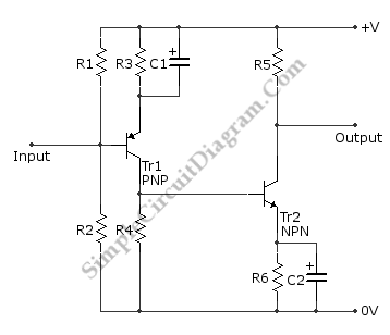
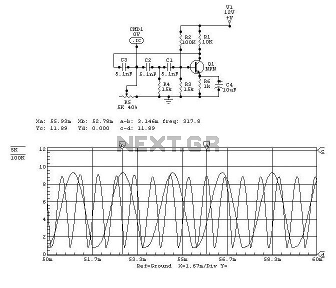
This is a directly coupled (DC) amplifier circuit. It is constructed using NPN and PNP transistors and is designed to amplify direct current (DC) signals. The directly coupled amplifier circuit utilizes both NPN and PNP transistors to achieve its amplification....
This achievement demonstrates the feasibility of creating a balanced dynamic microphone preamplifier, which is relatively straightforward. This preamplifier is particularly well-suited for microphones with an output impedance ranging from 200 ohms to 600 ohms. The advantages of this preamplifier...
The circuit automatically lights a bulb upon the arrival of a telephone ring and simultaneously mutes the audio from the music system or TV while the telephone handset is off-hook. The lighting of the bulb not only indicates an...
.gif)
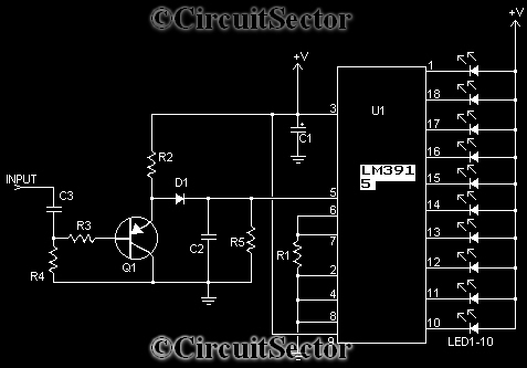
This circuit utilizes a single integrated circuit (IC) along with a minimal number of external components to display audio levels through ten LEDs. The input voltage range is from 12V to 20V, with a recommendation for 12V. The LM3915...
This device can also be referred to as an economical hearing aid, as it can be constructed using low-cost components. Although its performance does not match that of advanced commercially available hearing aids, it can effectively assist individuals with...
Warning: include(partials/cookie-banner.php): Failed to open stream: Permission denied in /var/www/html/nextgr/view-circuit.php on line 713
Warning: include(): Failed opening 'partials/cookie-banner.php' for inclusion (include_path='.:/usr/share/php') in /var/www/html/nextgr/view-circuit.php on line 713