
Twin-t-notch-filter
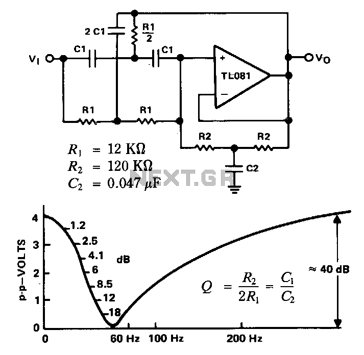
This filter is utilized to reject or block a specific frequency or range of frequencies. Such filters are commonly integrated into audio and instrumentation systems to eliminate a single frequency, for instance, 60 Hz. Commercial-grade components with a tolerance of 5% to 10% yield a null depth of at least 30 to 40 dB. An active filter can be implemented by combining a twin-T network with a TL081 operational amplifier in a circuit. The additional resistor-capacitor network, R2 and C2, operates effectively in parallel with the original twin-T network at the input of the filter. These networks determine the quality factor (Q) of the filter. The op-amp is configured as a unity-gain voltage follower. For a 60 Hz notch filter with a Q of 5, it is advisable to select the value of capacitor C1 and then calculate resistor R1. Let C1 be approximately 0.22 µF. Consequently, R1 should be around 12 kΩ, R2 around 120 kΩ, and C2 approximately 0.047 µF. Standard 5% resistors and 10% capacitors typically produce a notch depth of about 40 dB, as illustrated in the frequency response curve.
This circuit design describes a notch filter configuration that effectively attenuates a specific frequency while allowing other frequencies to pass with minimal distortion. The twin-T network is a passive filter topology that is particularly effective for generating a notch response at a designated frequency. The operational amplifier (TL081) serves as a buffer, providing high input impedance and low output impedance, which is essential for maintaining signal integrity and minimizing loading effects on the preceding stage of the circuit.
The quality factor (Q) of the filter is a critical parameter that determines the sharpness of the notch. A higher Q value results in a narrower bandwidth around the notch frequency, while a lower Q value produces a broader notch. In this configuration, the choice of C1 at 0.22 µF is strategic, as it influences the resonant frequency of the filter. The calculated resistor values, R1 at 12 kΩ and R2 at 120 kΩ, are selected to achieve the desired Q factor of 5, ensuring effective frequency rejection at 60 Hz.
Capacitor C2, valued at 0.047 µF, further fine-tunes the filter response, allowing for additional control over the frequency characteristics. The use of commercial-grade components with specified tolerances ensures that the filter will perform reliably within the expected parameters, achieving a notch depth of approximately 40 dB, as evidenced by the frequency response curve. This design is suitable for applications requiring precise frequency filtering, such as in audio processing or instrumentation systems where interference at specific frequencies must be minimized.This filter is used to reject or block a frequency or band of frequencies. These filters are often designed into audio and instrumentation systems to eliminate a single frequency, such as 60Hz. Commercial grade components with 5%-10% tolerance produce a null depth of at least 30 to 40 dB. When a twinT network is combined with a TL081 op amp in a circuit, an active filter can be implemented.
The added resistor capacitor network, R2 and C2, work effectively in parallel with the original twin-T network, on the input of the filter. These networks set the Q of the filter. The op amp is basically connected as a unity-gain voltage follower. For a 60-Hz notch filter with a Q of 5, it is usually best to pick the C1 capacitor value and calculate the resistor Rl. Let C1 ~ 0.22 JlF. Then: R 1 ~ 12 KO - R 2 ~ 120 KO - C2 ~ 0.047 JlF Standard 5% resistors and 10% capacitors produce a notch depth of about 40 dB, as shown in the frequency response curve.
🔗 External reference