Logarithmic amplifier
#logarithmic amplifier
#frequency compensation
#bias current compensation
#op-amp
#signal processing
#current measurement
#wide temperature range
#high resolution
#converter
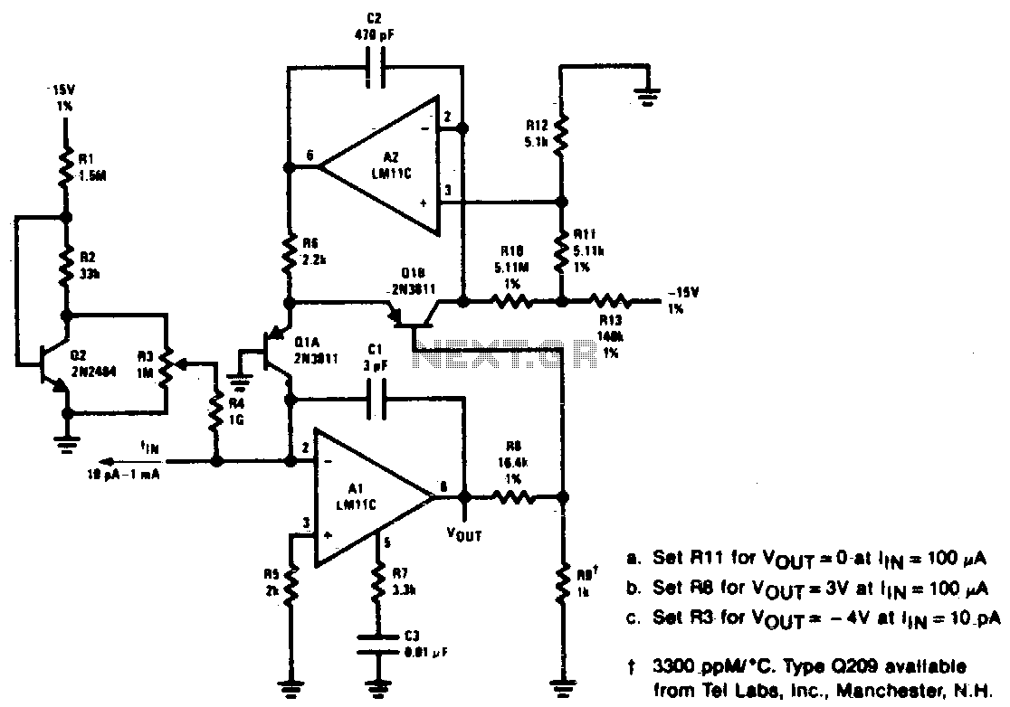
Description: Unusual frequency compensation provides this logarithmic converter with a 100 µs time constant from 1 mA down to 100 µA, increasing from 200 µe to 200 ms from 10 nA to 10 pA. Optional bias current compensation allows for 10 pA resolution across a temperature range of -55 °C to 100 °C. The scale factor is 1 V/decade and is temperature compensated.
This logarithmic converter is designed to offer precise current measurements over a wide dynamic range, making it suitable for applications requiring high sensitivity and accuracy. The frequency compensation mechanism is crucial, as it stabilizes the response time of the converter, allowing it to maintain a consistent time constant of 100 µs for input currents between 1 mA and 100 µA. As the input current decreases to lower levels, the time constant increases significantly, reaching up to 200 ms for inputs ranging from 10 nA to 10 pA.
The optional bias current compensation feature enhances the device's performance by enabling it to achieve a resolution of 10 pA. This feature is particularly beneficial in environments where temperature fluctuations may affect the performance of the circuit. The converter operates effectively across a broad temperature range from -55 °C to 100 °C, ensuring reliable operation in various conditions.
Moreover, the scale factor of 1 V/decade indicates that for every decade change in input current, the output voltage changes by 1 Volt. This logarithmic relationship is vital for applications such as signal processing, sensor interfacing, and data acquisition systems where precise current-to-voltage conversion is required. The temperature compensation ensures that the scale factor remains stable across the specified temperature range, further enhancing the accuracy and reliability of the measurements.
In summary, the unique frequency compensation and optional bias current compensation features of this logarithmic converter make it a highly effective tool for achieving precise current measurements across a wide range of conditions, with a focus on temperature stability and resolution.Unusual frequency compensation gives this logarithmic converter a 100 µs time constant from 1 mA down to 100 µA, increasing from 200 µe to 200 ms from 10 nA to 10 pA. Optional bias current compensation can give 10 pA resolution from - 55 °C to 100 °C Scale factor is 1 V/decade and temperature compensated.
