
Auto-battery-alternator-monitor
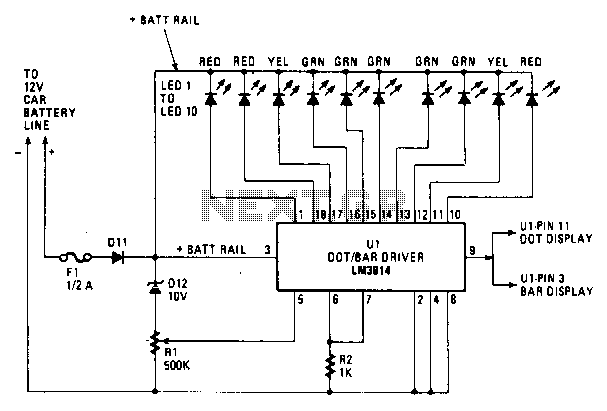
Most of the circuitry is contained in the LM3914 dot/bar-graph driver IC chip. In addition to the comparator circuitry within the package, it also contains a stable reference supply and the drivers for the LEDs. Resistor R2 acts as the current limiter for all the LEDs. Resistor R2 may be varied for LED brightness. The unit will illuminate one LED for each voltage condition encountered in the charging system. This system is called a dot-graph display; it is achieved by wiring the mode control at pin 9 to pin 11 on U1. It is possible to wire the monitor so that each lamp will be illuminated up to the maximum voltage on the line at that moment. The latter is referred to as a bar-graph display. By connecting pin 9 to pin 3 on U1, the bar-graph mode will be enabled.
The LM3914 is a versatile integrated circuit designed specifically for driving LED displays in either dot or bar graph configurations. The internal architecture of the LM3914 includes a precision voltage reference and a series of comparators that facilitate the display of analog voltage levels. The output pins of the chip are connected to multiple LEDs, with each LED representing a specific voltage threshold.
In this application, resistor R2 serves a critical role as a current limiting resistor. It controls the current flowing through the LEDs, affecting their brightness. By adjusting the value of R2, the designer can customize the brightness of the LEDs to suit the visibility requirements of the application. This feature is particularly useful in environments with varying ambient light conditions.
The configuration of the display can be switched between dot and bar modes. In dot mode, only one LED illuminates at a time, corresponding to the current voltage level detected. This mode provides a clear visual indication of the voltage level at any given moment. Conversely, in bar mode, multiple LEDs can be illuminated simultaneously, extending from the lowest to the highest voltage level present in the system. This is achieved by connecting pin 9 of U1 to pin 11 for dot mode and to pin 3 for bar mode.
The system is particularly useful in monitoring the charging conditions of batteries, where real-time voltage levels need to be displayed. The design can be integrated into various electronic applications, including battery management systems, power supply monitoring, and other voltage indication needs. Properly implemented, the LM3914 display system provides an intuitive and effective means of visualizing voltage levels in a compact and efficient format.Most of the circuitry is contained in the LM3914 dot/bar-graph driver IC chip. In addition to the comparator circuitry within the package, it also contains a stable reference supply and the drivers for the LEDs. Resistor R2 acts as the current limiter for all the LEDs. Resistor R2 may be varied for LED brightness. The unit will illuminate one LED for each voltage condition encountered in the charging system. This system is called a dot-graph display; it is achieved by wiring the mode control at pin 9 to pin 11 on Ul. It is possible to wire the monitor so that each lamp will be illuminated up to the maximum voltage on the line at that moment.
The latter is referred to as a bar-graph display. By connecting pin 9 to pin 3 on Ul, the bar-graph mode will be enabled. 🔗 External reference