
Auto battery current analyzer
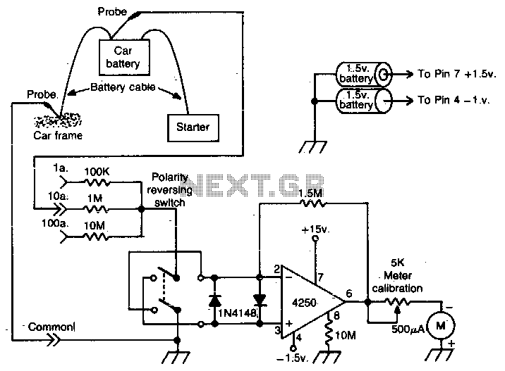
To calibrate the unit, the current flow should be measured at a specific location in the vehicle using a precise ammeter. Subsequently, the analyzer should be adjusted to match that current reading.
The op-amp analyzer utilizes a high-gain operational amplifier configured in a differential mode. This configuration allows for the accurate detection of small voltage differences, which is essential for measuring the low-level voltage generated across battery cables due to current flow. The input stage of the analyzer is connected to the battery terminals, where the small voltage drop is sensed.
The output of the op-amp is then processed, often through an analog-to-digital converter (ADC), to produce a readable current measurement displayed on an LCD or LED screen. This output can also be interfaced with a microcontroller for further data logging or analysis.
For calibration, it is crucial to ensure that the ammeter used for reference is both accurate and properly rated for the expected current range. The calibration process involves comparing the output of the analyzer against the reading from the ammeter and adjusting the gain of the op-amp until both readings align. This ensures that the analyzer provides accurate current measurements across various devices within the vehicle.
Additional features may include a low-pass filter to reduce noise, ensuring that the readings are stable and reliable. The design may also incorporate protective elements such as fuses to prevent damage to the analyzer from overcurrent conditions. Overall, this op-amp analyzer is a valuable tool for automotive diagnostics, allowing for precise monitoring of electrical consumption by various devices in a vehicle.This op-amp analyzer can measure the current drawn by any device in a car. The analyzer works by measuring the very small voltage that develops across the battery cables when current flows To calibrate the unit, measure the current flow somewhere in the car with an accurate ammeter, then adjust the analyzer for that current reading. 🔗 External reference
Related Circuits
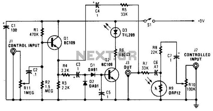
In this circuit, audio input to the control channel is amplified and rectified by diodes D1 and D2. This direct current level activates LED D3 through transistor Q2. The illumination from LED D3 causes R9, a light-dependent resistor, to...
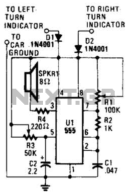
This circuit is designed to assist individuals with hearing impairments by generating a tone each time a dashboard turn indicator is activated. The frequency of the tone decreases for the duration that the indicator remains lit. The circuit operates by...
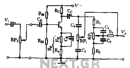
Pre-amplifiers utilize a tandem-type current feedback circuit, with an output impedance that is approximately equal to the DC collector resistance (Rc). The input impedance of the RC attenuator is equivalent to the load impedance of the amplifier. In the...
The project involves building an autofade table lamp based on a specific circuit diagram. The actual test circuit is depicted, with a note that resistor R1 from the schematic was omitted, as it was not necessary for the testing...

This circuit is designed to charge between one and twelve NiCd cells using a car battery. With switch S1 set to the normal position, it is capable of charging up to six cells. The circuit operates by utilizing a car...
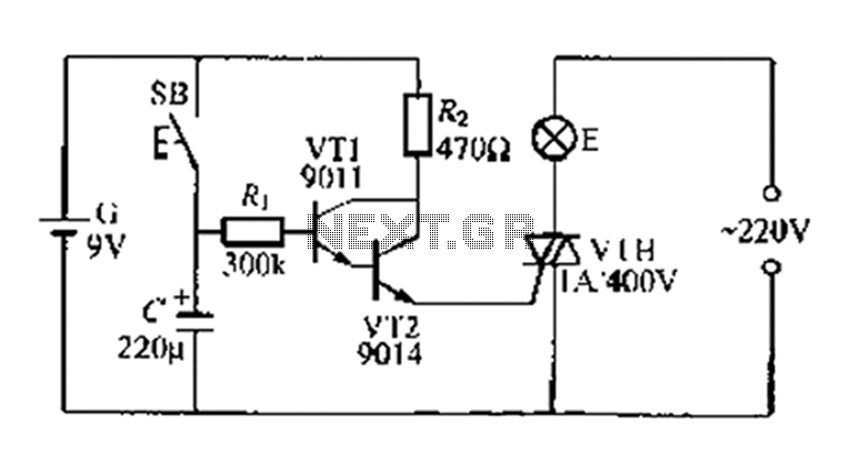
A delay circuit utilizing an electric lamp. Normally, the thyristor VTH remains off, and the lamp E does not illuminate. The lamp turns on when needed, controlled by the FSH, with the VT1 and VT2 components forming a composite...
Warning: include(partials/cookie-banner.php): Failed to open stream: Permission denied in /var/www/html/nextgr/view-circuit.php on line 713
Warning: include(): Failed opening 'partials/cookie-banner.php' for inclusion (include_path='.:/usr/share/php') in /var/www/html/nextgr/view-circuit.php on line 713