
Automatic dimming light circuit
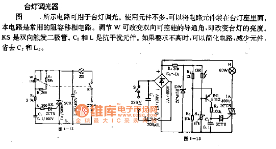
The lamp dimmer circuit operates based on the principles of phase control, allowing for the adjustment of the lamp's brightness by altering the phase angle at which the triac is triggered. The circuit typically consists of a triac, a variable resistor (W), a bi-directional trigger diode (KS), a capacitor (C2), and an inductor (L).
The triac serves as the main switching element, controlling the power delivered to the lamp. By adjusting the resistance of W, the phase angle can be varied, which in turn influences the point in the AC cycle at which the triac is triggered. A later trigger point results in a shorter conduction time for the triac during each half-cycle, effectively reducing the average power supplied to the lamp and dimming its brightness.
The bi-directional trigger diode (KS) is responsible for ensuring that the triac can be triggered during both the positive and negative halves of the AC waveform. This feature is essential for maintaining consistent dimming performance regardless of the AC polarity.
Capacitor C2 and inductor L form an RC network that helps to create the necessary phase shift for the triggering of the triac. The values of these components can be selected based on the desired dimming range and the characteristics of the lamp being used. It is important to ensure that the components used can handle the power levels involved to prevent overheating or failure.
Overall, this lamp dimmer circuit is an effective solution for controlling lamp brightness with a simple design that can be easily integrated into existing lamp fixtures.Lamp dimmer. The figure below shows the circuit can be used for lamp dimming. It uses a small quantity of components, which can be installed inside the lamp seat. The circuit is commonly used in RC phase shift circuit. W can be adjusted to change the triac conduction angle, which changes the lamp brightness. KS is a bi-directional trigger diode. C2 and L are.. 🔗 External reference
Related Circuits
This simple circuit is the electronic version of the combination lock. Using the special purpose LS7220 digital lock IC, the circuit allows a 4 digit combination of your choice to activate a relay for a set period of time....
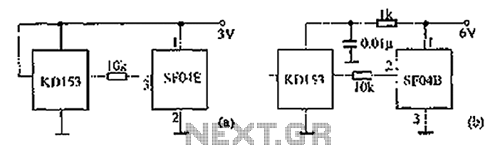
The circuit diagram illustrates the SF04E emission and the corresponding SF04B. Part (A) depicts the composition of the remote control transmitter SF04E, along with its compatible receiving circuit, which can be assembled using the SJ04H. Part (B) presents the...

UART, GPS. This application note illustrates how to integrate a GPS module SC16C2552B into a navigation system using a Philips UART. With the rapid advancement of GPS (Global Positioning System) technologies, GPS is being increasingly utilized across various sectors....
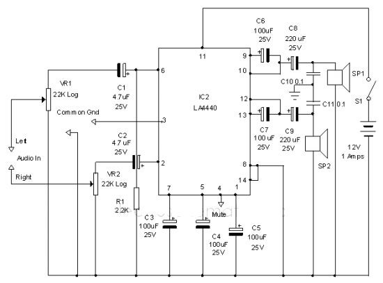
The LA4440 audio amplifier IC can be utilized to design a straightforward stereo power audio amplifier project, capable of delivering 6 watts of output power into an 8-ohm load. This audio amplifier IC features a minimal number of external...
The team is highly interested in the design of a jammer circuit and has begun working on it. However, they are experiencing issues with the circuit, specifically that the signal is not being jammed effectively. The design of a jammer...
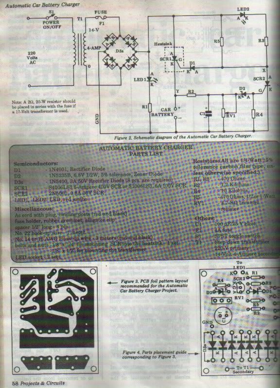
This project is designed for individuals interested in constructing their own Automatic Battery Charger. It has been developed by duc_tech. The Automatic Battery Charger project involves creating a circuit that can efficiently charge batteries without requiring constant supervision. The design...