
automatic dual output display circuit diagram

The circuit operates through a combination of digital logic components and timing mechanisms to achieve a dynamic lighting effect. The oscillator formed by gates N1 and N2 generates a consistent clock signal that drives the BCD counter CD4510 (IC2). This counter is capable of counting both up and down, depending on the state of pin 10, which determines the counting direction. The output from pin 7 of IC2 acts as a pulse generator that indicates when the counter reaches its terminal counts (9 for counting up and 0 for counting down).
The decade counter CD4017 (IC3) is configured as a toggle flip-flop, which means it alternates its output state based on the incoming clock pulses from the inverted output of IC2. This toggling action is crucial for creating the sequential lighting effect, as it ensures that the output at pin 3 of IC3 changes state, allowing for a smooth transition between the counting phases.
The BCD output from IC2 is connected to the decoder CD4028 (IC4), which activates the corresponding triacs for each bulb. The triacs serve as electronic switches that control the power to the bulbs, allowing them to be turned on and off in a controlled manner. During the count-up phase, the bulbs illuminate in a forward sequence, while the count-down phase reverses the order, enhancing the visual display.
This circuit exemplifies the integration of digital logic with power control elements to create a visually engaging lighting system suitable for various applications, including decorative displays and educational demonstrations in electronic principles.This circuit lights up ten bulbs sequentially, first in one direc- tion and then in the opposite direction, thus presenting a nice visual effect. In this circuit, gates N1 and N2 form an oscillator. The output of this oscillator is used as a clock for BCD up/down counter CD4510 (IC2). Depending on the logic state at its pin 10, the counter counts up or down. During count up operation, pin 7 of IC2 outputs an active low pulse on reaching the ninth count. Similarly, during count-down operation, you again get a low-going pulse at pin 7. This terminal count output from pin 7, after inversion by gate N3, is connected to clock pin 14 of decade counter IC3 (CD4017) which is configured here as a toggle flip-flop by returning its Q2 output at pin 4 to reset pin 15. Thus output at pin 3 of IC3 goes to logic 1 and logic 0 state alternately at each terminal count of IC2.
Initially, pin 3 (Q0) of IC3 is high and the counter is in count-up state. On reaching ninth count, pin 3 of IC3 goes low and as a result IC2 starts counting down. When the counter reaches 0 count, Q2 output of IC3 momentarily goes high to reset it, thus taking pin 3 to logic 1 state, and the cycle repeats. The BCD output of IC2 is connected to 1-of-10 decoder CD4028 (IC4). During count-up operation of IC2, the outputs of IC4 go logic high sequentially from Q0 to Q9 and thus trigger the triacs and lighting bulbs 1 through 10, one after the other.
Thereafter, during count-down operation of IC2, the bulbs light in the reverse order, presenting a wonderful visual effect Disclaimer: All the information present on this site are for personal use only. No commercial use is permitted without the prior permission from authors of this website. All content on this site is provided as is and without any guarantee on any kind, implied or otherwise.
We cannot be held responsible for any errors, omissions, or damages arising out of use of information available on this web site. The content in this site may contain COPYRIGHTED information and should not be reproduced in any way without prior permission from the authors.
🔗 External reference
Related Circuits
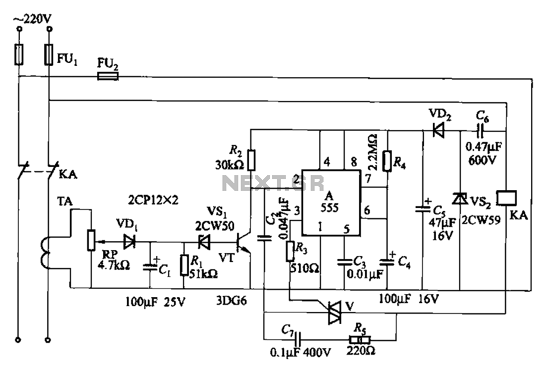
The 555 limit circuit, which is an integrated electrical circuit, is designed to manage large electrical loads. It automatically disconnects power when the load exceeds a predetermined threshold. Once the load is reduced below this threshold, power is restored...
The remote control robot circuit is illustrated in the accompanying figure. Figure 2-36(a) presents the circuit diagram, while figure 2-36(b) depicts the operating timing diagram. The robot's rotation process involves an ultrasonic launching circuit, which consists of a 40...
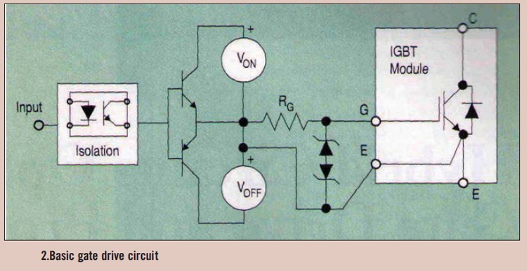
High power IGBT modules utilize hybrid integrated circuit (IC) gate drives that incorporate protection circuits, which implement desaturation detection or real-time control. High power Insulated Gate Bipolar Transistor (IGBT) modules are essential components in various high-efficiency power conversion applications, such...

This design circuit functions as a sine wave oscillator, providing both sine and square wave outputs across a frequency range from below 20 Hz to above 20 KHz. The oscillation frequency can be easily adjusted by varying a single...
This circuit is designed to power a lamp or other appliance for a specified duration of 30 minutes, after which it automatically turns off. It is particularly useful for nighttime reading, as it can turn off a bedside lamp...
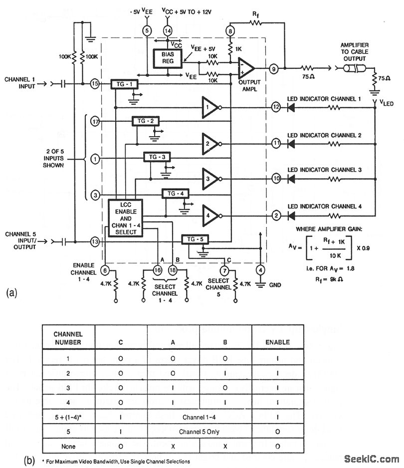
This circuit illustrates a CA3256 switch/amplifier configured for a direct-coupled output. One of four channels can be selected in parallel with channel 5. The analog switches of channels 1 to 4 are digitally controlled by logic. A VEE of...