Automatic Emergency Lighting Unit
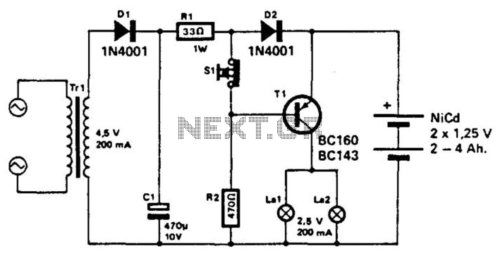
This unit utilizes a NiCad battery to supply power to an emergency lighting system. During a power failure, transistor T1 becomes forward biased, activating lamps L1 and L2. The batteries are typically maintained in a charged state. When the power is restored, T1 is turned off, extinguishing the lamps.
The emergency lighting system described is designed to provide illumination during power outages, ensuring safety and visibility in critical situations. The core component of the system is the NiCad (Nickel-Cadmium) battery, which serves as a reliable power source due to its ability to be recharged and its relatively high energy density.
In normal operating conditions, when the main power supply is active, T1, a transistor, remains in the off state, effectively preventing any current from flowing to the lamps L1 and L2, thus keeping them turned off. The circuit is designed to automatically switch to battery power when the main power fails.
Upon detection of a power failure, T1 transitions to the on state, becoming forward biased. This allows current to flow through the circuit, illuminating both lamps L1 and L2. The activation of these lamps provides necessary lighting in emergency situations.
The system includes a charging circuit that ensures the NiCad battery remains charged while the main power is available. This is critical for maintaining readiness for unexpected power outages. The charging circuit typically includes a resistor and a diode to regulate the charging process and prevent backflow of current when the main power is off.
The design may also incorporate additional safety features such as fuses or circuit breakers to protect against overcurrent conditions, ensuring the longevity and reliability of the emergency lighting system. Overall, this circuit is an essential component for emergency preparedness in residential, commercial, and industrial applications. This unit uses a Nicad battery to provide power to an emergency lighting setup. When power fails, T1 beco mes forward biased, which lights LI and L2. The batteries are normally kept charged. When power is on, T1 is cut off and it keeps the lamps extinguished. 🔗 External reference
