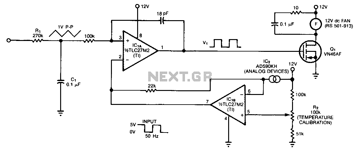
Automatic-fan-speed-controller

The controller circuit is designed to reduce a fan's noise, power consumption, and wear, especially when operating in low, fluctuating ambient temperatures. A temperature sensor is mounted in the fan's airstream, allowing the circuit to adjust the fan speed as needed to maintain a relatively constant temperature at the sensor. Input components R1 and C1 integrate the input square wave, resulting in a quasi-triangular wave at the non-inverting input of operational amplifier IC1A. The inverting input receives a reference voltage that decreases as temperature increases. The two-terminal sensor generates a current of 1 pA/K, producing a rectangular wave at the output of IC1A, with a duty cycle that is proportional to the absolute temperature. Consequently, an increase in temperature activates a cooling response by supplying more power to the fan. To calibrate the system with the sensor at room temperature, R2 can be adjusted to achieve a 50% duty cycle at the input voltage. The fan will turn off at approximately 0°C and will operate at full capacity at 44°C.
The controller circuit employs a feedback mechanism to optimize fan performance based on real-time temperature readings. The temperature sensor, strategically placed within the airflow of the fan, is critical for accurate temperature monitoring. It outputs a small current that corresponds to the temperature, which is then processed by the operational amplifier (IC1A). The quasi-triangular wave generated by the integration of the input square wave serves as a modulation signal for the fan's operation.
The reference voltage at the inverting input of IC1A is carefully calibrated to ensure that as the ambient temperature rises, the output of the operational amplifier adjusts the duty cycle of the fan control signal accordingly. This adjustment enables the fan to increase its speed, thereby enhancing cooling when temperatures exceed the set threshold. Conversely, when the temperature drops, the circuit reduces the fan speed, minimizing noise and energy consumption.
Component R2 plays a vital role in the system's calibration process. By adjusting R2, the designer can set the desired duty cycle at room temperature, ensuring that the fan operates efficiently across the specified temperature range. The design also incorporates safety thresholds; the fan will deactivate at approximately 0°C to prevent damage from low temperatures and will fully engage at 44°C to provide optimal cooling.
Overall, this controller circuit exemplifies an efficient approach to managing fan operation in response to temperature fluctuations, thus enhancing performance and longevity while reducing unnecessary noise and power consumption.The controller circuit can reduce a fan"s noise, power consumption, and wear, particularly in the presence of a low, fluctuating ambient temperature. Mount a temperature sensor in the fan"s airstream, and the circuit will adjust the fan speed as necessary to maintain a relatively constant sensor temperature.
Input components Rl and Cl integrate the input square wave, producing a quasitriangular wave at the noninverting input of op amp IC1A. At this inverting input is a reference voltage that decreases as temperature increases. The two-terminal sensor produces 1 p.A/0 K. The resultis a rectangular wave at the output of IClA with a duty cycle proportional to absolute temperature. Thus, a rise in temperature triggers a counteracting cooling effect by delivering more power to the fan.
To calibrate the system with the sensor at room temperature, simply adjust R2 for a 50% duty cycle at Vi. The fan will switch off at approximately 0°C and will be fully on at 44°C.