
Automatic-headlight-delay
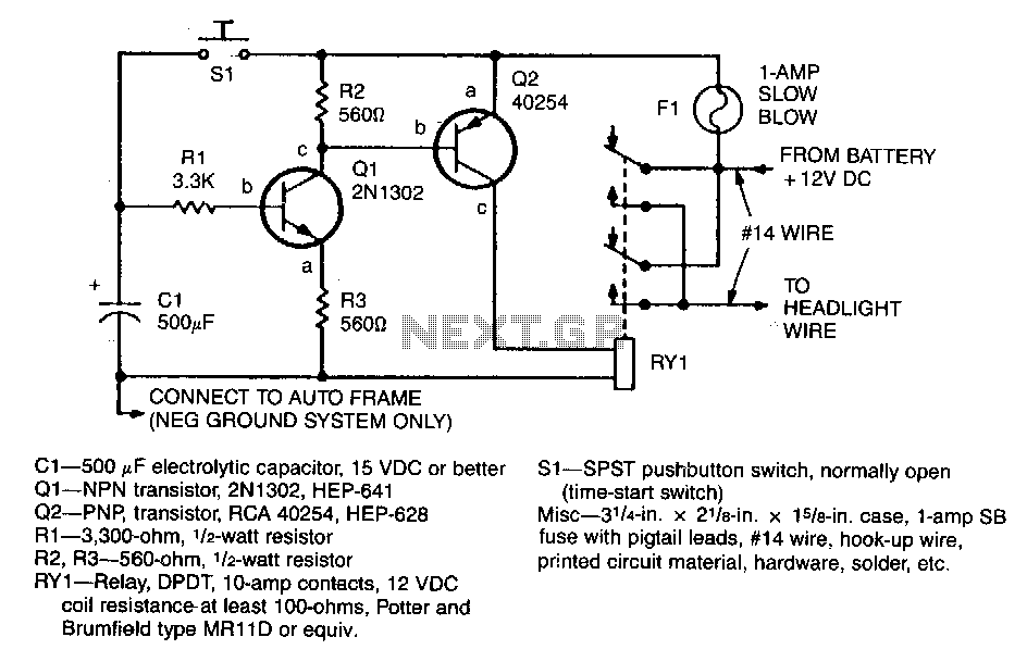
When the driver presses pushbutton switch S1, timing capacitor C1 charges to 12 V, activating transistor Q1, which in turn drives power transistor Q2 into conduction. This action energizes the relay, which has its contacts connected in parallel with the headlight switch. The relay remains energized until C1 discharges to the turn-off level of Q1. The duration for which the lights remain on is determined by the values of C1, R1, and the characteristics of transistor Q1. With the values specified in the schematic, approximately 60 seconds of illumination are provided.
C1 is a 500 µF electrolytic capacitor rated for 15 VDC or higher. S1 is a single-pole, single-throw (SPST) pushbutton switch, normally open. Q1 is an NPN transistor, specifically a 2N1302, used as a time-start switch. Q2 is a PNP transistor, an RCA 40254. Additional components include a 3.30 k-ohm, 1/2-watt resistor (R1), a 560-ohm, 1/2-watt resistor (R2), and a relay (AY1) with double-pole, double-throw (DPDT) configuration, rated for 1 amp with 12 VDC coil resistance of at least 100 ohms. The circuit also requires miscellaneous materials such as a case measuring 3.4 in. x 2.5 in. x 1.5 in., fuse with pigtail leads, #14 wire, hook-up wire, printed circuit material, hardware, solder, etc.
The circuit operates by utilizing a pushbutton switch to initiate a timing sequence. Upon pressing S1, capacitor C1 begins to charge, and once it reaches the threshold voltage of 12 V, it activates Q1. This NPN transistor allows current to flow to Q2, which is a PNP transistor. The conduction of Q2 energizes the relay, closing its contacts and effectively bypassing the headlight switch, thus keeping the lights on. The relay remains engaged until C1 discharges to a level that can no longer maintain Q1 in the 'on' state.
The timing characteristics of the circuit are influenced by the RC time constant, determined by the product of the capacitance of C1 and the resistance of R1. The specified values allow for a lights-on duration of approximately 60 seconds, providing a practical solution for scenarios where delayed lighting is beneficial. The relay used must have a coil resistance that meets or exceeds 100 ohms to ensure proper operation within the circuit's design parameters. Overall, this schematic provides an effective method for controlling headlight operation with a timed delay.When the driver depresses pushbutton switch S1, timing capacitor C1 charges to 12 V and turns on transistor Q1, which drives power transistor Q2 into conduction. This, in tum, energizes the relay which has its contacts connected in parallel with the headlight switch.
The relay will stay energized unW C1 discharges to the Q1 tum-off level. The lights-on period is determined by the value of C1, R1, and the characteristics of transistor QL With values chosen on the schematic, about 60 light-on seconds are provided. C1-500 uF electrolytic capacitor, 15 VDC or better $1-SPST pushbutton switch, normally open 01-NPN transistor, 2N1302, HEP-641 (time-start switch) 02-PNP, transistor, RCA 40254, HEP-628 Misc-31/4-in. x 21/e-in. x 15/e-in. case, 1-amp SB R1-3,30D-ohm, 1/2-watt resistor fuse with pigtail leads, #14 wire, hook-up wire, R2, A3-560-ohm, 11.2-watt resistor printed circuit material, hardware, solder, etc.
AY1-Aelay, DPDT, Hl-amp contacts, 12 VOC coil resistance-at least 100-ohms, Potter and TAB BOOKS Brumfield type MA11D or equiv. 🔗 External reference