
Automatic light activated switch circuit
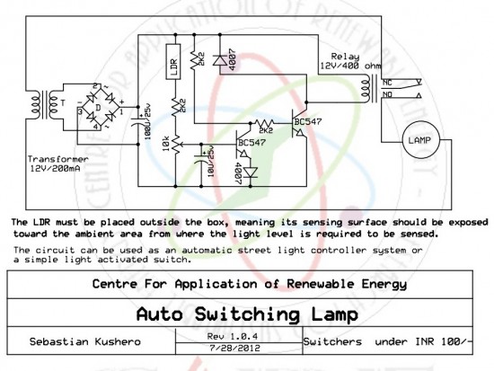
The described circuit utilizes a light-dependent resistor (LDR) as the primary sensor to monitor ambient light conditions. When the light intensity falls below a predefined threshold, the LDR's resistance decreases, triggering the circuit to activate the connected lamp(s). Conversely, when the ambient light increases, the resistance of the LDR increases, causing the circuit to deactivate the lamp(s).
The power supply section is crucial for ensuring stable operation. It typically includes a step-down transformer to reduce the AC mains voltage to a lower level, a bridge rectifier to convert AC to DC, and a filter capacitor to smooth the output voltage. This clean DC voltage is essential for the reliable operation of the circuit components, including the LDR, transistors, or relays used for switching.
In practical applications, the LDR should be installed in a location where it can accurately gauge the surrounding light conditions, such as on a streetlight pole or in a garden. The circuit can also incorporate additional components like potentiometers to adjust the sensitivity of the LDR, allowing customization based on specific environmental conditions.
For enhanced functionality, the circuit may include a timer or a microcontroller to provide more advanced features, such as programmable lighting schedules or integration with other smart home systems. This versatility makes it suitable for various applications, including residential lighting control, street lighting, and garden lighting systems, ultimately promoting energy efficiency by ensuring lights are only active when necessary.The circuit can be used for switching OFF a particular lamp or group of lamps in response to the varying ambient light levels. The unit once built can be used for switching OFF a lamp when dawn breaks and switching it ON when dusk sets in.
The power supply is a standard transformer, bridge, capacitor network, which supplies a clean DC to the circui t for executing the proposed actions. The LDR must be placed outside the box, meaning its sensing surface should be exposed toward the ambient area from where the light level is required to be sensed. The circuit can be used as an automatic street light controller system or a simple light activated switch.
🔗 External reference
Related Circuits

A tone generator circuit, which can be used to create a simple calling bell circuit, is illustrated here. It is constructed using the 8021 integrated circuit (IC), which includes built-in circuitry for producing a "ding-dong" sound. The tone generator circuit...

Two gates of a 4011 IC are utilized as a comparator. When the resistance of R4 decreases, the voltage at pins 1 and 2 increases, resulting in a logic zero at pin 3. This causes pin 4 to go...
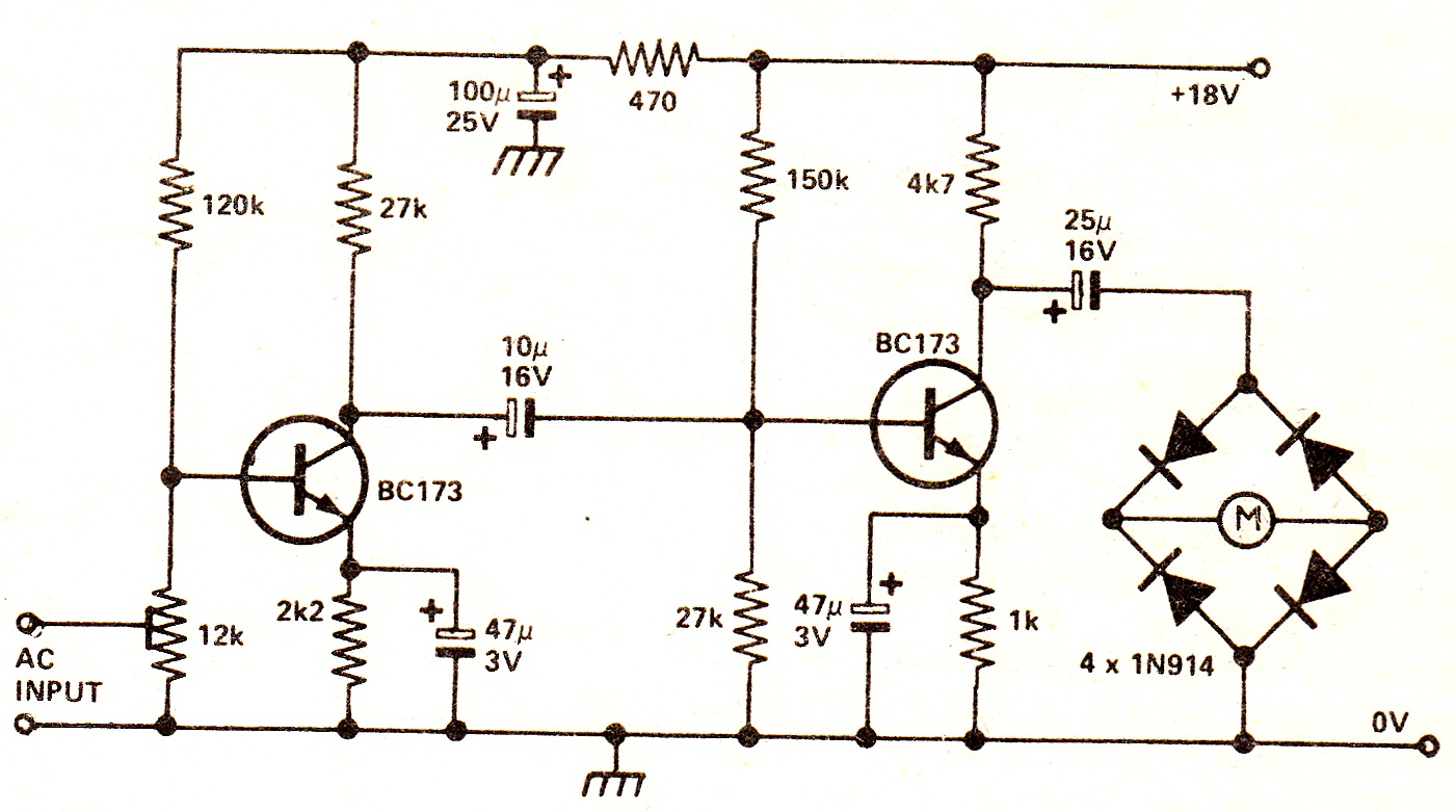
The circuit illustrates a two-stage voltage amplifier that drives a recording level meter. An AC signal input is amplified and rectified, with the resulting DC voltage displayed on the meter. This circuit is compatible with tape recorders or audio...
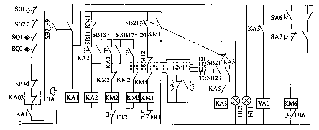
The operation control circuit is primarily managed by the button switch SB21. The contactor KM1, composed of the main contactor KM1, directly controls the operation of the main motor M1. The main motor M1 serves as the prime mover,...

This design circuit is for audio graphic equalizers, which are commonly found as commercial products, yet published circuits for them are quite rare. The circuit features a simple design that requires an operational amplifier (op-amp) to amplify the input...

DTMF-based Robo Car design using the 8051 microcontroller project. This project demonstrates a method to control a domestic system using the DTMF tone generated by a telephone instrument when the user presses the keypad buttons of a mobile phone...