
Automatic Light Dimmer

The circuit operates as a dimmer switch for incandescent lamps, utilizing a combination of capacitors, resistors, diodes, and a triac to control light intensity. The integration of the components begins with the activation of switch S1. This initiates the charging of capacitor C2 through the resistive network formed by R1 and C1, along with the bridge rectifier comprising diodes D1 through D4. The rectifier converts the AC voltage to DC, allowing C2 to charge effectively. The Zener diode D5 serves a crucial role in voltage regulation, ensuring that C2 does not exceed 15 V, which is essential for protecting sensitive components in the circuit.
As the circuit stabilizes, the activation of diode D6 signals the presence of sufficient voltage across R3, a light-sensitive resistor that responds to the LED's illumination. The triggering of triac Tr1 occurs when the voltage across R3 reaches a threshold, allowing current to flow to the incandescent lamp, thus illuminating it.
When the light switch is turned off, the discharge path for C2 is established through potentiometer P1, resistor R2, and diode D6. This discharge process is key to the dimming functionality, as the gradual decrease in voltage across C2 leads to a corresponding reduction in the brightness of the LED. The resulting decrease in light intensity causes an increase in the resistance of R3, which in turn adjusts the phase angle of the triac, allowing for a smooth dimming transition rather than an abrupt cutoff.
The adjustable dimming time is a significant feature of this circuit, controlled by potentiometer P1. This flexibility allows users to customize the dimming effect based on personal preference or specific application needs. The design also emphasizes the importance of the LDR's placement, as it must be shielded from external light sources to ensure that the circuit operates as intended. Overall, this dimmer circuit exemplifies a practical application of electronic components to achieve user-friendly lighting control.In many cases, the dimmer presented here may be built into a wall-mounted box containing the light switch. It is intended for use with 240 V incandescent lamps only. When it is fitted, and the light is switched on, the lamp does not come on fully for about 400 ms (which is not noticeable).
When the light is switched off, it stays on unchanged for about 20 s, and then goes out gradually. This has the advantage that it is not immediately dark when the light is switched off. When light switch S1 is turned on, capacitor C2 is charged via R1, C1 and bridge rectifier D1 D4. Zener diode D5 limits the potential across C2 to about 15 V. After a short while, diode D6 lights, whereupon a potential difference ensues across light sensitive resistor R3, which is sufficient to trigger triac Tr1. The light then comes on. When the light switch is turned off, C2 is discharged via P1, R2 and D6. When the potential across C2 drops, the brightness of the LED diminishes, so that the p. d. across R3 also drops. The increasing resistance of R3 effects phase angle control of the triac so that the light is dimmed gradually.
The dimming time may be altered with P1 within the time range determined by network R2-C2. The circuit operates correctly only, of course, when the LDR is not exposed to light other than that from the LED. The type of LDR is not particularly important, as long as it is not too long: in the prototype, a model with a length of 5 mm was used.
🔗 External reference
Related Circuits

The circuit presented in the above schematic has been designed to charge automatically two series 350mAh "AAA" size batteries. Set the 20KOhms multiturn potentiometer to get a 2.78V on the 3rd pin of the LM311 which is a comparator....
With a 1.5V battery supply, the integrated circuit LM3909 can drive the light-emitting diode NSL5027. The 300μF electrolytic capacitor acts as a timing capacitor, which limits the flash speed to approximately 1Hz. The circuit utilizes the LM3909, a popular LED...
The function of this circuit is to detect a sudden shadow falling on the light sensor and to activate a buzzer when this occurs. The light sensor is designed to monitor ambient light levels. The circuit utilizes a light-dependent resistor...

This custom mod gives your computer the personality of KITT, the computerized car from Knight Rider TV fame. The project is a light display which imitates the dot in KITT's hood. It looks like the scanning eye of the...
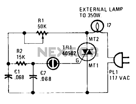
A heatsink allows the TRIAC (TR1) to manage a maximum power of 350 watts. The neon lamp, II, will not activate the gate until the TRIAC begins conducting, and resistor R1 can be adjusted to set the desired lighting...

The circuit of the running light consists of two integrated circuits (ICs), a resistor, a capacitor, and seven light-emitting diodes (LEDs), along with a decade scaler IC. The running light circuit is designed to create a sequential lighting effect using...