
Automatic Street Light Controller Circuit Using Relays and LDR
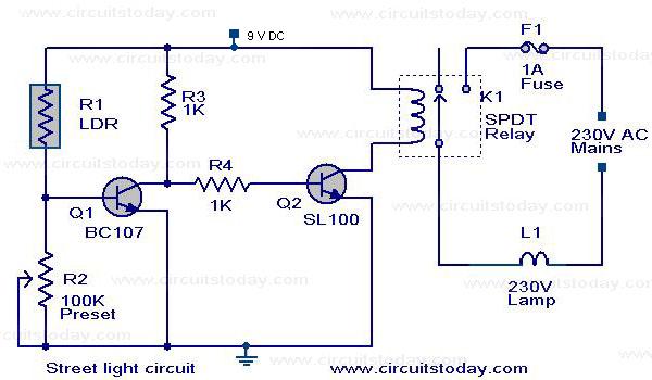
The Automatic Street Light Controller Circuit is designed to automatically turn on street lights at dusk and turn them off at dawn. This functionality is achieved using a light-dependent resistor (LDR) as the primary sensor. The LDR detects ambient light levels; when the light falls below a certain threshold, the resistance of the LDR decreases, triggering a transistor that activates the street light.
The circuit typically consists of the following components: an LDR, a resistor for voltage division, a transistor (commonly an NPN type), and a relay to control the high voltage of the street light. The LDR is connected in a voltage divider configuration with a fixed resistor, creating a voltage that varies with light intensity. This voltage is fed into the base of the transistor, which acts as a switch.
When the ambient light level decreases, the voltage across the LDR and resistor combination drops, allowing the transistor to turn on. This, in turn, energizes the relay, closing its contacts and powering the street light. Conversely, when the light levels increase at dawn, the LDR's resistance increases, causing the transistor to turn off and deactivating the relay, thus turning off the street light.
The circuit can also include additional features such as time delay circuits or dimming capabilities to enhance functionality. Overall, the Automatic Street Light Controller Circuit is an efficient solution for managing outdoor lighting, reducing energy consumption, and improving street safety.The circuit diagram of an Automatic Street Light Controller Circuit is explained in this post.. 🔗 External reference
Related Circuits
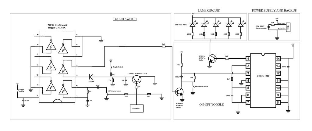
A touch switch for a USB-powered desk lamp is malfunctioning. The circuit diagram, layout, and pictures are provided below. The design incorporates circuits sourced from two websites, specifically the fourth circuit. The output of the touch switch is connected...
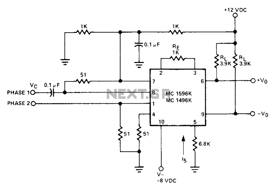
The circuit involves a Signetic balance modem connection utilizing a transistor array as a phase detector. It provides information about the cosine of the phase angle, which corresponds to the frequency of the input signal combined with the integrated...
This circuit detects the dial tone from a telephone line and decodes the keypad pressed on the remote telephone. The dial tone heard when picking up the phone is known as Dual Tone Multi-Frequency (DTMF). The term is derived...
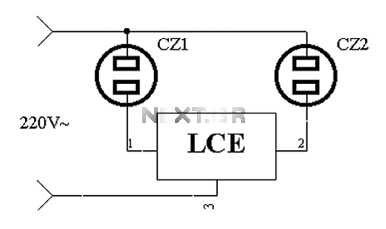
The application circuit operates the device as illustrated below. It is designed for cooling electrical equipment, typically utilizing a cooling fan to dissipate heat. The LCE employs a synchronous control socket on the device and its connections remain unchanged....
The proximity detector detects the movement of PC board pieces as the wheel rotates, generating an output signal with a clear transition between high and low voltage levels, making it suitable for triggering counting or processing circuits. Following this...
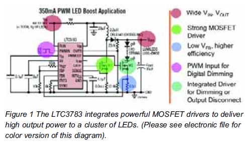
High brightness (HB) and super HB LEDs are utilized in LCD TFT backlighting for high-end televisions, industrial lighting, and projectors. A notable application is in instrument panel backlighting, interior lighting, and brake lights of various vehicles. Luxury automobile manufacturers...
Warning: include(partials/cookie-banner.php): Failed to open stream: Permission denied in /var/www/html/nextgr/view-circuit.php on line 713
Warning: include(): Failed opening 'partials/cookie-banner.php' for inclusion (include_path='.:/usr/share/php') in /var/www/html/nextgr/view-circuit.php on line 713