
DC Motor Controller

The described DC Motor Controller circuit is designed to manage the operation of a 12V DC motor through a user interface comprising three pushbuttons: START, REVERSE, and STOP. The circuit operates under specific conditions that govern the motor's directional control and stopping mechanisms.
Initially, the circuit maintains the motor in a non-operational state. Upon pressing the START button, the motor is activated and begins to rotate in a predetermined direction, which can be defined by the circuit configuration. The implementation of this functionality typically involves a relay or an H-bridge driver, which allows for the control of the motor's direction and power.
While the motor is in operation, pressing the REVERSE button has no effect, thereby preventing any unintended direction changes during active operation. This feature is critical for applications requiring consistent motor performance without interruption. The STOP button serves as an emergency or standard halt mechanism, immediately ceasing motor operation regardless of the current state.
In the event that the motor is stopped, pressing the REVERSE button will initiate the motor's operation in the opposite direction, effectively allowing for a change in direction only when the motor is not actively running. Conversely, if the motor is running in the REVERSE direction, pressing the START button will not alter its operation.
The circuit can be implemented using basic electronic components such as transistors, diodes, and resistors, alongside the pushbuttons for user input. Additional features such as indicator LEDs may be included to signal the current state of the motor (running, stopped, or reversing). Proper power supply considerations for the 12V motor and the control circuit must also be taken into account to ensure reliable operation.This DC Motor Controller circuit will control a 12V dc motor. The system will have three pushbuttons: a START button, a REVERSE button and a STOP button. Initially, the motor must not be running. When the START button is pressed, the motor will run in one direction. Pressing the REVERSE button (while the motor is running in START direction) must have no effect on the motor. Pressing the STOP button must stop the motor from running. Pressing the REVERSE button while the motor is stopped will make the motor run in a direction (opposite to the direction for the START button). Pressing the START button (while the motor is running in REVERSE direction) must have no effect on the motor.
P 🔗 External reference
Related Circuits
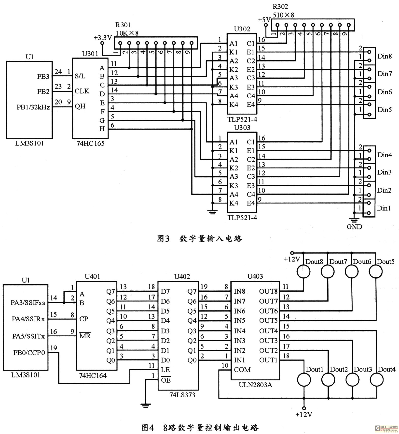
The figure utilizes a controller as the primary equipment for gathering and controlling digital data within an on-site monitoring system. The stability of on-site control operations is crucial to the overall system performance. Therefore, a simple and stable structure...
No description available. More: Q1, Q2: Standard-Transistoren D1: SB130 Q3: RFD 15 N 05 IC1A: CD4011B (if SMD) IC1B: detto The provided components suggest a basic electronic circuit that incorporates both transistors and integrated circuits, along with a diode. The circuit...
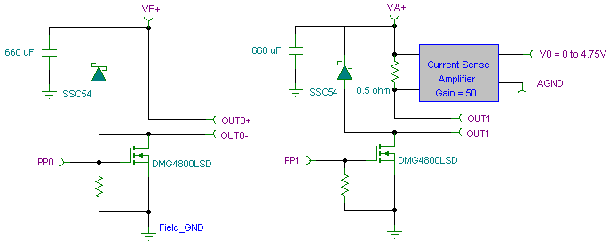
The PWM pulse width modulation controller board enables 9S12/HCS12 microcontrollers or PIC microcontrollers to output 8 channels, each capable of delivering 5 DC amps, while incorporating current sensing for the PWM waveform. This PWM driver circuit is suitable for...
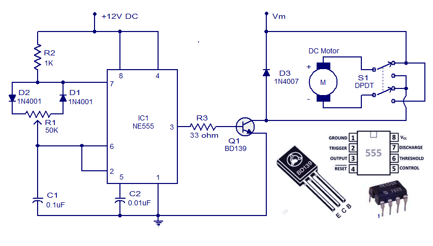
This weblog discusses electronic circuit schematics, PCB design, DIY kits, and electronic project diagrams. A simple DC motor controller circuit utilizing the NE555 timer is presented. Several DC motor speed control circuits are explored, with this being the first...
The modified power-factor controller, developed at the Marshall Space Flight Center, utilizes a phase detector for each of the three phase windings of a delta-connected induction motor. The control mechanism is based on the sum of the phase differences. Instabilities...
The Intelligent Fan Controller regulates the speed of computer fans according to the internal temperature of the computer, minimizing noise levels. It utilizes a 4-wire, 2-wire, and 3-wire fan configuration in conjunction with a PIC microcontroller, specifically the PIC18F2550....