
autotronics injector circuit
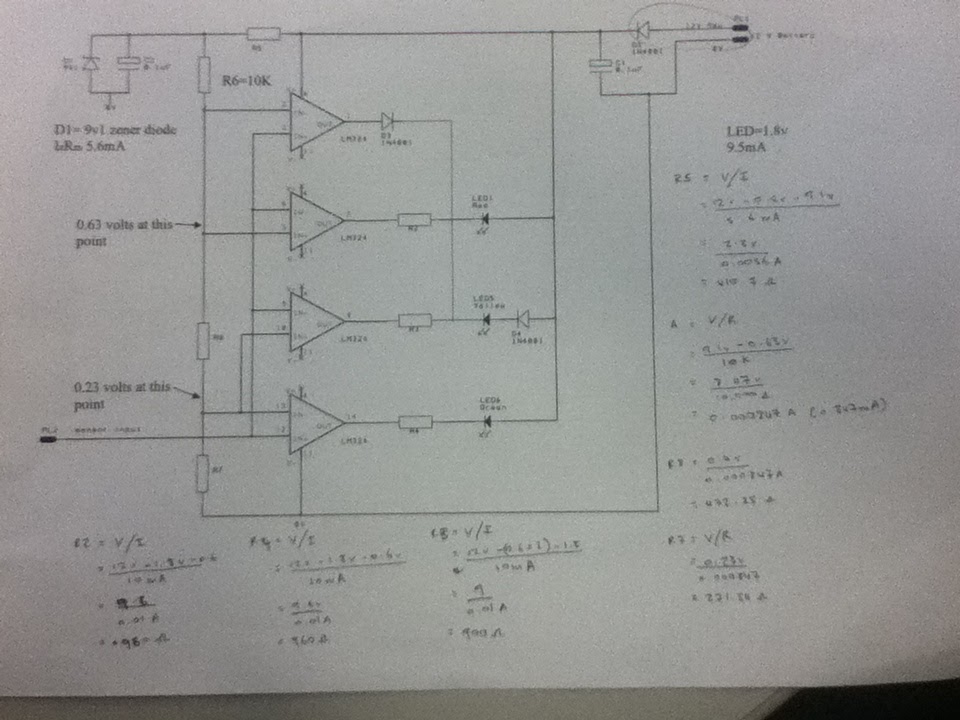
The schematic represents a comprehensive oxygen sensor circuit utilizing operational amplifiers to manage LED indicators based on voltage inputs simulating sensor conditions. Each operational amplifier is configured to amplify the signal from the sensor input, with specific resistor values calculated to achieve desired voltage drops and ensure proper LED operation. The circuit design incorporates protection elements such as diodes and capacitors to maintain stable operation and prevent voltage spikes, enhancing reliability during testing scenarios. The use of MOSFETs further allows for efficient switching and control of the LED indicators based on the varying voltage levels received from the sensor input. Overall, this circuit design exemplifies a practical application of operational amplifiers and MOSFETs in automotive sensor technology, providing visual feedback through LEDs in response to sensor readings.The above diagram shows the different links to theinputs and outputs of each operational-amplifier from the power source and how each operation amplifier is wired to operate each seperate light emitting diode. Also shows calculations to obtaining each resistor value which is shown in previous blog. The above equipment was used to to supply voltage to the sensor input of the oxygen sensor circuit. This was used to test the oxygen sensor circuit by turning one of the dials on the machine which would send different votage signals to the sensor input, depending on the amount of voltage you turned the DC power supply would determine which circuit of the oxygen sensor would operate. This machine was used to simulate the throttle of a vehicle. the higher you turned the dial would simulate you putting your foot down on the accelerator. Starting with a 12 volt power supply voltage flows through the diode which leaves available vlotage of 11.
4 as it causes a 0. 6 voltage dropto the resistor (r5) to the 9. 1volt zener diode and capacitor. the capacitors are put in the circuit to prevent voltage surges and to keep a steady voltage flow. Also from the power supply, after diode it has a connection to the op-amp before the resistor (r5) to pin 4 of the op-amp, that is known as the positive voltage rain of the op-amp. From the zener diode it voltage flows to the next resistor (r6) but because of the zener thier is only 9.
1volts availabe. after the resistor it breaks off to pin 2 of the first op-amp and then pin 5 of the second op-amp, and because of the resistance put in the circuit we have 0. 63 volts available at both pin 2 and pin 5. In a straight connection after r6 and after pin 2 and pin 5 inputs voltage flows to the next resistor (r8) which then connects to pin 10 of the third op-amp and pin 13 of the fourth op-amp, and again because of adding the resistance created a 0.
4voltage drop so at pin 10 and pin 13 has available voltage of 0. 23 volts. Each op-amp has an output, those pins are numbered as pins 1, 7, 8 and 14. pins 7, 8 and 14 eachconnect to and individual LED which has a positive feed from the 12volt power supply after the diode which leaves 11. 6 volts available to each LED, but at pin 8 from the anode side of the LED has a another diode. Between the LED andoutput pins 7, 8 and 14 have resistors r2, r3 and r4. The output pin1 has and diode connected to it which connects to pin 8 in between the resistor and LED on the cathode side of the LED.
Each LED with the power supply on is hot at all times. since pin 13 is a higher voltage it creates an output connection between pin 11 and pin 14. so the positive voltage from the power supply to the LED will go to ground and doing so will switch the green LED on. The yellow will remain off as the voltage is not high enough at 9whichmeans thier is a connection from pin 4 to pin 8 and has a positive feed to to the cathode of the LED which keeps the yellow LED off while the green is on.
When the voltage at the sensor input reaches about roughly 3volts at pin 9 will create a output connection between pin 11 and 8 as the input voltage is higher than 0. 23volts at pin 13 which means voltage can flow from the power supply through the yellow LED to pin8 to pi 11 through to ground will will indeed operate the LED.
in doin this it will switch the green LED off as pin 12 will also have a 3volt input wihch is higher than 0. 23 volts at pin 13 which will create a connection between pin 4 and 14 which means positive voltage will flow from pin 14 to the cathode of the LED which will switch the LED off.
When the voltage reaches roughly 0. 7-0. 8volts will turn the red LED as thevoltage at pin 5 of the input is lower than the voltage of pin 6 which creates a connection between pin 7 and 11 which allows the voltage from the power supply to go to ground which should operate thered LED. As the input voltage at pin 9 is still higher than the input a pin 10 (op-amp used to switch yellow LED) the yellow LED should still remain on so we`ve connected output pin 1 between the yellow LED and the resistor.
when sensor inputs 0. 7 volts will switch on the LED and also create a connection between pin 4 and pin 1 which which allows positive voltage to flow from pin 1 to the cathode side of the yellow LED to switch it off while the red LED is on. I had another person create a fault in my oxygen sensor circuit. I called see it visualy but i wanted to know how that fault was affecting the circuit. So i attached it to the 12 volt power supply and found only the yellowLED remained on at all times no matter if you turned the sensor input voltageup or down.
So using a multimeter set on DC volts, I refered to the wiring diagram and went through the circuit looking at available voltages. From the power supply after the diode was 11. 4volts available. After r5 to the zener diode showed 9. 1volts which showed that part of the circuit was fine. Placed the meter before the r6 resistor which showed 9. 1 volts which is good then after r6 which showed 9. 1 volts again when it should have showed 0. 63. Than checked before resistor r8 and pin 10 and 13 which showed 1. 8milivolts which is next to nothing. In doing this check showed thier was a break after input pin 5 but before resistor r8. So this showed me why the red LED will not turn on as thier is always 9. 1 volts at pin 2 and 5 and the sensor will never reach that high of a voltage because if it did will blow the LED.
but was still confused why the yellow LED remained on the whole time. So again using the multimeter checked the available voltage at pin9 and 12 when the DC power supply is set at 0 volts a got a reading of 8. 2milivolts, which is known as floating voltage. Since that is still higher than the 1. 8 milivolts at pin 10 the yellow LED will remain on. -The MOSFET is used just like any other transistor where it can be used as a switch in a circuit or used to amplify voltage.
just like the Bipolar Junction Transistor (BJT) it has three main terminals. Where the terminals in the BJT are called Base, Collector and Emitter. The names change in the MOSFET, the terminals are the Gate, Drain and the Source. Also the difference between the BJT and the MOSFET is the BJT requires high current to the Base of the transistor to allow voltage to flow from the collector to the emitter where in the MOSFET it requires voltage at the Gate to allow voltage to flow from the Drain to the Source. The N-Channel Mosfet acts like a NPN bipolar junction transistor where the base of the BJT needs a positive feed to turn on the N-channel Mosfet requires positive voltage at the Gate to turn on.
The greater the Gate voltage the increases the size of the channel created. The P-Channel MOSFET acts like a PNP BJT where the PNP requires a negative feed to the base, so it requires zero voltage to allow voltage to flow the collector to the emitter the MOSFET requires zero voltage at the Gate to allow voltage to flow from the drain to the source but requires positive voltage to switch it off. These MOSFET`s can either be of a Depletion type where it requires voltage at the Gate to turn on or Enhancement type where the voltage at the Gate is used to turn the MOSFET on.
It has two input terminals and an output terminal and a negative and positive voltage rail. The positive input is known as the inverting terminal and the negative known as the non-inverting terminal and basically the op-amp amplifies the difference between the to inputs. The above digram shows four op-amps three LED`s three diode`s one zener diode and seven resistors all wired together to create an oxygen sensor circuit.
But before wiring the circuit together i have to find the values of different resistors to use in the circuit to produce different outputs at each op-amp. Firstly i find the resistor value which is after the power supply and diode so we will call that R5. Also taking not it has a 9. 1volt zener diode off that same circuit i created a formula using the ohm`s law. resistance = voltage/amperage. Also knowing the amperage required to operate the zener diode at 5. 6mA therefore Then going on to find the resistor values for r7 and r8 i have to find the amperage that will flow through as it is a parallel circuit and amperage may vary.
As r6 is already given as 10k (10, 000 ohms) and the available voltage after the zener diode is 9. 1volts and the available voltages given after each resistor 🔗 External reference
Related Circuits
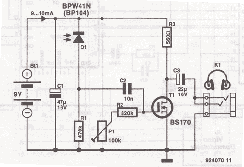
This wireless headphones transmitter ensures quality reception over a distance of 2 meters. The oscillator frequency ranges from 1750 kHz to 3500 kHz, and for the antenna, it... The wireless headphones transmitter operates within a frequency range of 1750 kHz...

The schematic for this project is visually acceptable, although it is not the most refined layout for a schematic. The basic flow progresses from left to right, starting with the state machine, followed by the 555 timers, then the...
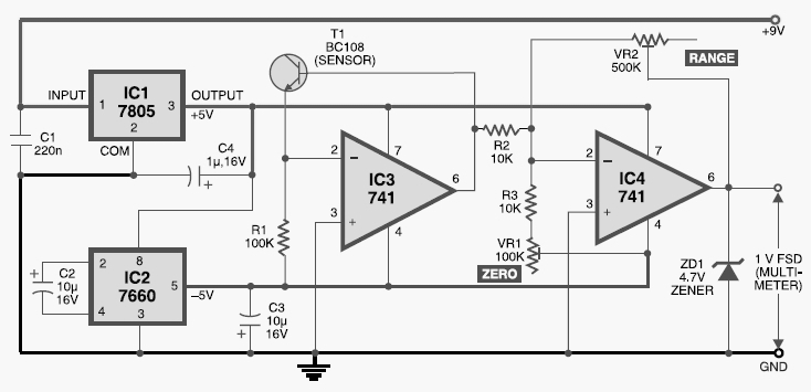
This digital thermometer circuit diagram uses a common 1N4148 diode as the temperature sensor. The temperature coefficient of the diode is -2 mV/°C. The digital thermometer circuit leverages the characteristics of the 1N4148 diode, which has a well-defined temperature coefficient....
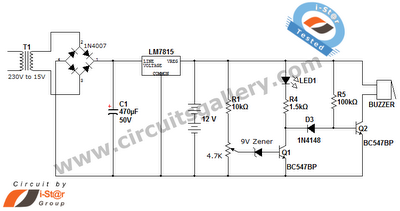
This is a straightforward 12V rechargeable smart battery charger circuit. It can be utilized as a charger for car batteries, inverter batteries, emergency light batteries, and more. An automatic indicator alarm circuit accompanies this battery charger schematic. The primary...

This direct-conversion receiver utilizes a TDA7000 integrated circuit (IC) and incorporates an LM386 audio amplifier. The TDA7000 serves as the mixer and local oscillator (L.O.) section. The frequency control can be achieved using either an air variable capacitor or...
This circuit below shows a teleremote circuit that enables the switching on and off of appliances through telephone lines. It can be used. The teleremote circuit operates by utilizing telephone lines to control electrical appliances remotely. The primary components of...