
Averager and Peak Hold/Extender Signal Conditioner
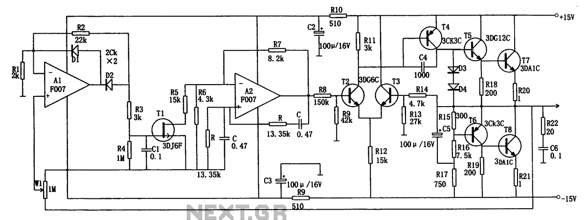
The signal averager circuit utilizes two operational amplifiers (op-amps) to achieve signal averaging through amplification and rectification. The first op-amp functions as a non-inverting amplifier, which boosts the input signal to a desired level while maintaining its phase. The output of this amplifier feeds into the second op-amp configured as an active rectifier. This active rectifier converts the amplified AC signal into a DC level, allowing for averaging over time.
The circuit typically includes feedback resistors that determine the gain of the amplifiers, along with diodes that ensure the rectification process only allows positive voltages to pass, effectively eliminating negative portions of the signal. Capacitors may also be incorporated to smooth out the output, providing a more stable average value.
In practical applications, this signal averager circuit can be used in various fields such as audio processing, sensor signal conditioning, and any scenario where it is necessary to obtain the average value of fluctuating signals. The careful selection of component values is critical to ensure the desired frequency response and accuracy of the averaging process.A signal averager circuit can be formed by an amplifier and active signal rectifier, which is implemented using two operational amplifiers in this circuit. The.. 🔗 External reference
Related Circuits
The low-frequency signal generating circuit demonstrates excellent performance characterized by stable operation, high output power, and minimal waveform distortion. It serves as an ideal source for low-frequency measurement signals. The circuit includes an operational amplifier (A) with a feedback...
A small audio test generator is very useful for quickly tracing a signal through an audio unit. Its main purpose is speed rather than refinement. An audio test generator is an essential tool in the field of audio engineering, primarily...
A symmetrical millivolt peak-to-peak triangle waveform can be generated by the circuit illustrated in the schematic diagram below. This circuit is equipped with... This circuit employs an operational amplifier (op-amp) configured in an integrator setup to produce a triangle waveform. The...
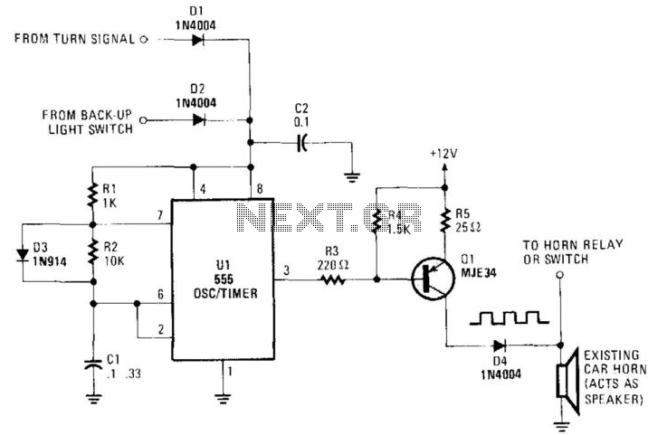
An auto horn operates as a speaker within a limited audio-frequency range. This circuit utilizes a 555 timer configured as an oscillator to drive an MJE34 transistor, which subsequently activates the horn. Normal horn operation is maintained through the...
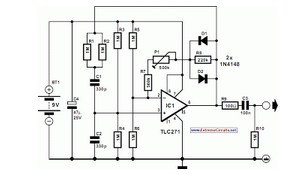
This circuit greatly expands upon the capabilities of circuit 02. A thermocouple signal is quite small, and the long thermocouple leads often induce quite a bit of noise into the system. This new circuit is far more accurate, stable,...
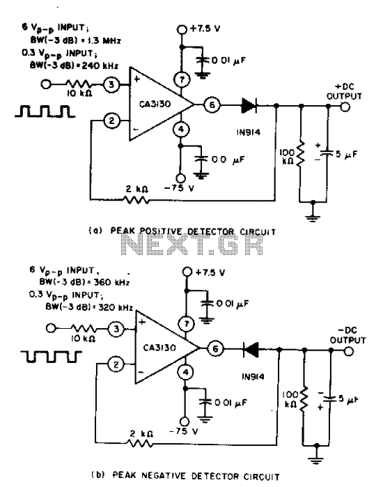
Circuits can be readily constructed using the CA3130 BiMOS operational amplifier. When dealing with large-signal inputs, the bandwidth of the peak-negative circuit is lower than that of the peak-positive circuit. The second stage of the CA3130 serves to limit...
Warning: include(partials/cookie-banner.php): Failed to open stream: Permission denied in /var/www/html/nextgr/view-circuit.php on line 713
Warning: include(): Failed opening 'partials/cookie-banner.php' for inclusion (include_path='.:/usr/share/php') in /var/www/html/nextgr/view-circuit.php on line 713