
BA5173 produced by multi-function lamp dimmer
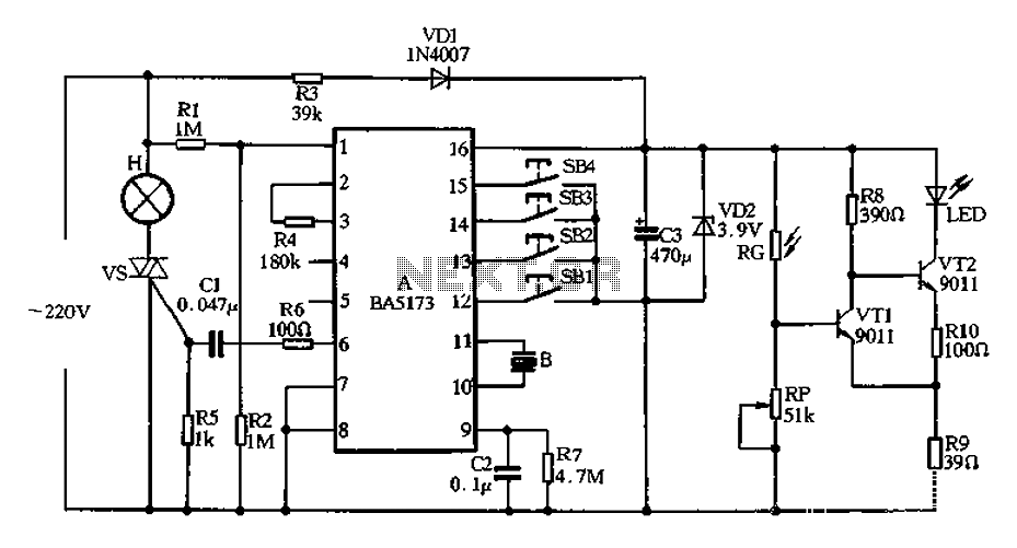
The circuit's design integrates several key components and functionalities that enhance its usability and effectiveness in managing light levels for eye protection. The buck converter configuration utilizing R3 efficiently steps down the AC voltage to a manageable DC level suitable for the BA5173 block. The rectification and filtering stages ensure stable voltage supply, critical for the reliable operation of the control logic and output stages.
The Schmitt trigger circuit involving VT1 and VT2 provides a robust method for detecting light intensity changes. The use of a photoresistor RG in conjunction with the Schmitt trigger allows for a responsive and reliable indication of ambient light levels. The chosen threshold of 100 lux serves as an effective point for activating the LED indicator, providing immediate feedback to users regarding their lighting conditions.
The control buttons (SB1 to SB4) introduce a user-friendly interface for adjusting light settings. The stepless dimming feature via SB1 allows users to gradually adjust brightness levels, accommodating varying preferences and needs. The stepped dimming function of SB2 offers simplicity with predefined levels, making it easy for users to switch between different brightness settings quickly. The delay-off feature of SB3 promotes energy efficiency and convenience, particularly useful in scenarios where users may forget to turn off the lights. Finally, the automatic on/off function of SB4 encourages regular breaks, thereby supporting eye health during extended reading or studying sessions.
Overall, this circuit design is a practical solution for managing lighting conditions in educational settings, combining functionality with user-centric features to promote eye safety and comfort.220V AC by R3 buck figure, VDI rectifier, VD2 and C3 filtered output voltage of about 3,9V DC supply set to block BA5173 electricity. Rl is manifold zero-crossing detector curr ent limiting resistor, R4 for the manifold external oscillation resistor, R7, C2 POR use, phasing BA5173 output trigger pulse through R6, CI added SCR vs gate to control the conduction angle. VTI, VT2 composition Schmitt circuit, it photoresistor RG and other elements constituting the metering display circuit, when the light shines greater than lOOlx (lux), the photosensitive resistor RG of less resistance, VT1 conduction, VT2 off, LED does not send light.
When the light intensity is less than lOOlx, RG resistance value increases, the Schmitt trigger circuit flip. VTI off VT2 conduction, LED light, indicating light is too weak, until transferred lamp dimmer so that the light intensity is greater than lOOlx, LED was extinguished.
This electrical path to avoid students under low light illumination to read and write, and thus play a role in eye protection. The circuit has four control buttons switches SB1 ~ SB4, each key switch the following functions: SBI: stepless dimming control keys.
When you use this key lights can be set to an arbitrary level, press this key, the lights fade from the dark, and then by repeated cycles of the brightest fade infinitely variable, when the light intensity reaches the extreme position (the brightest or darkest) when, the piezoelectric ceramic sheet B will uttered pops sound as a reminder, when transferred to the appropriate brightness, let go after the luminance namely memory retention. SB2: stepped dimming controls. Press the chain once, the light intensity changes in a block, press the low light, the light, the brightest and off 4 -speed dimming cycle.
SB3: Delay Off control keys. Button once, lights, after about half a minute after the lamp turns off automatically. It is suitable to sleep at night or when leaving the room to go out with. SB4: time automatic on/off control button. Press the button, lights, lights automatically turn off after about 20min, another 5nun light, bright 20rrun, repeated cycles. It is mainly used to remind students not read for a long time, in order to protect the eyesight, can also be used for night time outside confuse no one at home, so that thieves will not dare to patronize.
One thing to note, no matter what kind of light is dimming state, when the lamp is lit, to turn off the lights, just a short temporary Touch SB1 ~ SB4 any of a button, the lights are off. Readers can choose according to the actual needs of the above-mentioned one or several dimming mode.
Related Circuits
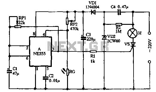
VDI, VD2, C3, and C4 form a simple half-wave rectifier capacitor step-down regulator circuit. This circuit can output approximately 12V DC voltage after power is applied across C3, which is utilized for the time base circuit. Additionally, the time...
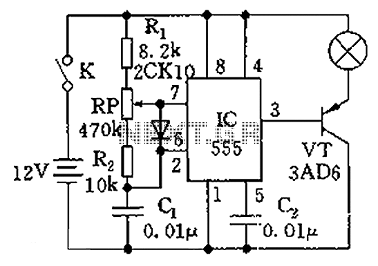
The circuit illustrated in the figure is a dimmer using the 555 timer as the core component. The 555 timer, along with resistors R1, RP, R2, and capacitor C1, forms an astable multivibrator. The oscillation frequency, f, is calculated...
This little circuit can be used to dim lights up to about 350 watts. It uses a simple, standard TRIAC circuit that generates very little heat. Please note that this circuit cannot be used with fluorescent lights. This circuit...
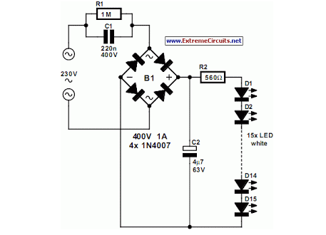
An array of white LEDs can serve as an effective small lamp for the living room. LED lamps are commercially available. LED arrays are increasingly popular for providing ambient lighting in residential spaces. The use of white LEDs in a...
Switching to alternative power sources can lead to savings on electricity bills. The photovoltaic module or solar panel discussed here has a power output of 5 watts. Under full sunlight conditions, the solar panel generates 16.5V and can provide...
This automatic light dimmer circuit enables the gradual control of a lighting system, allowing it to turn on or off slowly. The operation of the circuit is as follows: when switch S1 is closed, capacitor C1 charges slowly. Once...
Warning: include(partials/cookie-banner.php): Failed to open stream: Permission denied in /var/www/html/nextgr/view-circuit.php on line 713
Warning: include(): Failed opening 'partials/cookie-banner.php' for inclusion (include_path='.:/usr/share/php') in /var/www/html/nextgr/view-circuit.php on line 713