
Backup Beeper
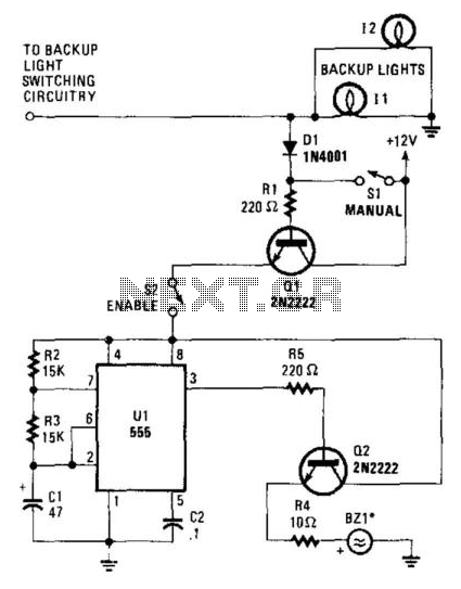
The described circuit is designed to provide an audible warning when a vehicle is in reverse. The operation begins with the activation of the vehicle’s backup lights or the manual switch (SI). This action allows a small current to flow into the base of transistor Q1, which acts as a switch that controls the larger current flowing through the circuit.
When Q1 is activated, it allows current to pass through to the enable switch (S2). If switch S2 is closed, it energizes the 555 timer (U1) with a supply voltage of 12 V. The 555 timer is configured in astable mode, producing a continuous square wave output. The timer generates high pulses of approximately 0.97713 seconds and low signals of about 0.488565 seconds. These pulses are directed to the base of transistor Q2.
Transistor Q2 functions as a power amplifier in this circuit. When it receives the signal from the 555 timer, it switches on, allowing a higher current to flow from the power supply to the piezoelectric buzzer (BZ1). The buzzer is designed to emit sound when supplied with this current, thereby alerting individuals in proximity to the vehicle that it is in reverse.
For effective sound projection, it is recommended that BZ1 be mounted in a location under the vehicle where the sound can travel unobstructed. This ensures that the warning beeps are audible to pedestrians and other drivers, enhancing safety during reversing maneuvers. Proper placement of the buzzer is critical for maximizing the effectiveness of the warning system. When the vehicle"s backup lights kick on, or when the manual switch (SI) is closed, a small current is fed to the base of Ql. Transistor Ql allows current to flow through it and, if the enable switch (S2) is closed, it sends 12 V to Ul, a 555 timer. Timer Ul sends high pulses that last 0.97713 s and low signals that last 0.488 565 s to the base of Q2.
When Ul switches Q2 on, it sends 12 V to BZ1, a piezoelectric buzzer. For best results, the buzzer should be mounted under the vehicle—somewhere where people around the car can hear the warning beeps. 🔗 External reference
Related Circuits

When the light on the answering machine blinks, the resistance of photoresistor Rl increases, triggering the timer (U1) and generating a 0.2-second pulse that activates BZ1. Rl is optically coupled to the LED on the answering machine and is...
After installation in the car (not running but in reverse with the emergency brake engaged), the system functioned well. However, when the car was started and reversed out of the garage, the beeping frequency became erratic while tapping the...
A low-cost DC adapter can be utilized to construct a stabilized and uninterruptible 9V power supply. For safety and cost-effectiveness, a simple unstabilized 12V DC adapter serves as the power source; a universal adapter set to 12V will also...
Pressing P1 resets IC2, which then begins oscillating at a frequency determined by R3 and C1. With the specified values, this frequency is approximately 4Hz. LED D2, controlled by IC1A and IC1B, flashes at the same oscillator frequency, indicating...

Typically, the base of a cordless phone is equipped with an adaptor, while the handset operates using Ni-Cd cells. In the event of a power failure, the base unit becomes inoperative. To address this issue, it is advisable to...
This schematic illustrates a beeper circuit designed to produce a continuous beep sound while simultaneously flashing an LED. The beeper circuit typically consists of a few key components: a sound-generating device (such as a piezo buzzer), an LED for visual...
Warning: include(partials/cookie-banner.php): Failed to open stream: Permission denied in /var/www/html/nextgr/view-circuit.php on line 713
Warning: include(): Failed opening 'partials/cookie-banner.php' for inclusion (include_path='.:/usr/share/php') in /var/www/html/nextgr/view-circuit.php on line 713