
BALANCED MODULATOR DEMODULATOR
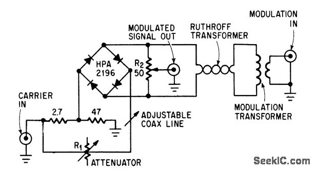
The described circuit is a diode quad modulator designed to effectively suppress carrier signals by 65 dB, as indicated in the reference by W. H. Ellis. This suppression is critical in applications where signal fidelity is paramount, such as in communication systems. The use of closely matched diodes is essential for maintaining consistent performance across the modulation spectrum.
In this configuration, R1 serves as the primary amplitude adjustment component, allowing the user to fine-tune the output signal's amplitude to meet specific requirements. The coaxial line, which is integral to the circuit, is used for precise phase adjustment, ensuring that the modulation is aligned correctly with the carrier signal. This alignment is crucial for minimizing distortion and maximizing the quality of the output signal.
R2, while providing a more minor adjustment, plays a significant role in refining the overall performance of the circuit. By allowing slight variations in amplitude, R2 aids in achieving optimal signal characteristics, which can be particularly beneficial in systems where signal levels may fluctuate due to varying operational conditions.
The overall design emphasizes the importance of component matching and careful adjustment to achieve high levels of suppression, making this circuit suitable for advanced communication applications where clarity and precision are required.Achieves high carrier and modulation suppression by using closely matched diodes and providing R1 for amplitude adjustment and coaxial line for phase adjustment. R2 provides slight amplitude adjustment. -W. H. Ellis, Diode Quad Modulator Suppresses Carrier 65 Db, Electronics, 39:8, p 97. 🔗 External reference
Related Circuits
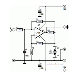
The pulse width of the compact pulse cum frequency modulator can be varied by altering the change-over point of comparator IC1 with a control voltage. The compact pulse cum frequency modulator utilizes a comparator IC, designated as IC1, to modulate...
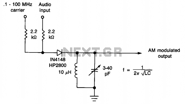
This simple diode modulator provides excellent performance for high percentage modulation at low signal levels. The constants are specified for a carrier frequency of approximately 10 MHz; however, with an appropriate tank circuit, the design can achieve satisfactory results...
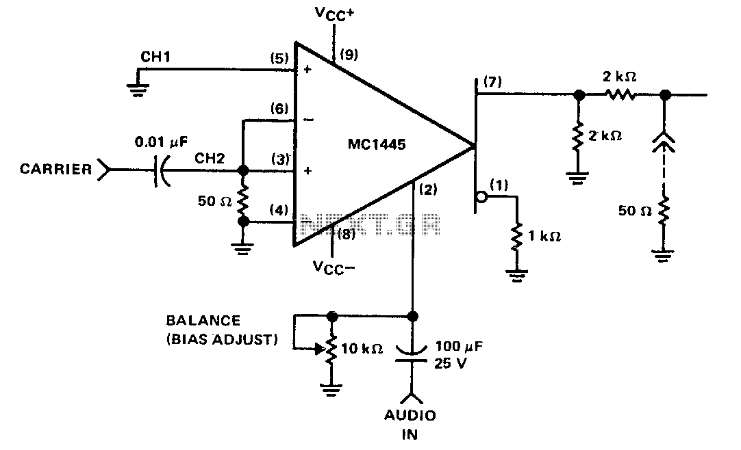
When the carrier level is sufficient to activate the cross-coupled pair of differential amplifiers, the modulation signal applied to the gate will be switched at the carrier frequency between the collector loads. This switching results in the modulation being...
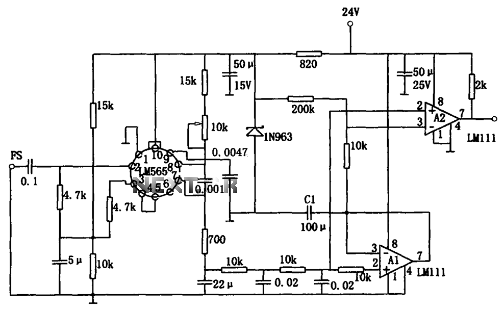
The sensitive frequency demodulation circuit utilizes the LM565 integrated circuit in a phase-locked configuration, allowing it to track frequency offsets across a wide range. However, at small frequency offsets, the signal can produce a minimal demodulated output, causing the...
The TBA120 Series integrated circuits (ICs) offer a high-gain limiting intermediate frequency (IF) amplifier and a quadrature coincidence detector in a single package. These ICs are primarily designed for the extraction of television intercarrier sound, which is frequency modulated...
This is a schematic diagram of a pulse width to analog demodulator circuit. This circuit is used to demodulate the pulse width to an analog voltage level. The pulse width to analog demodulator circuit is designed to convert pulse-width modulated...
Warning: include(partials/cookie-banner.php): Failed to open stream: Permission denied in /var/www/html/nextgr/view-circuit.php on line 713
Warning: include(): Failed opening 'partials/cookie-banner.php' for inclusion (include_path='.:/usr/share/php') in /var/www/html/nextgr/view-circuit.php on line 713